Fangs "new" toy!!

Post your pictures here: your bikes, meets you've attended, modifications you've made, x-rays you've had taken...
Post Reply
User avatar
nuggitt
Moderator
Moderator
Posts: 5968
Joined: Fri May 22, 2009 9:45 pm
Location: North Yorkshire

Post by nuggitt »

Good to see you back and glad you're still at it lad.

I think that light looks rather well on her. You have my vote on that one. :thumbsup: :thumbsup: :thumbsup:

I want to know how many handbags you own. :unibrow:
Bit of advice. Buy a good bed and a good pair of shoes, because if you aren't in one you'll be in the other.
User avatar
nuggitt
Moderator
Moderator
Posts: 5968
Joined: Fri May 22, 2009 9:45 pm
Location: North Yorkshire

Post by nuggitt »

That is looking rather well and the headlight looks pretty neat. You've got some nice flowing lines there mate. :nod: :thumbsup:
Bit of advice. Buy a good bed and a good pair of shoes, because if you aren't in one you'll be in the other.
User avatar
fang
Pit-lane Reporter
Pit-lane Reporter
Posts: 741
Joined: Mon Jun 19, 2006 5:38 pm
Location: Bootiful Norfolk

Post by fang »

Cheers Nuggitt, yep getting there slowly, baby steps and all that. :D
Never Ever Bloody Anything Ever!!!
User avatar
fang
Pit-lane Reporter
Pit-lane Reporter
Posts: 741
Joined: Mon Jun 19, 2006 5:38 pm
Location: Bootiful Norfolk

Post by fang »

Right then, another small update.

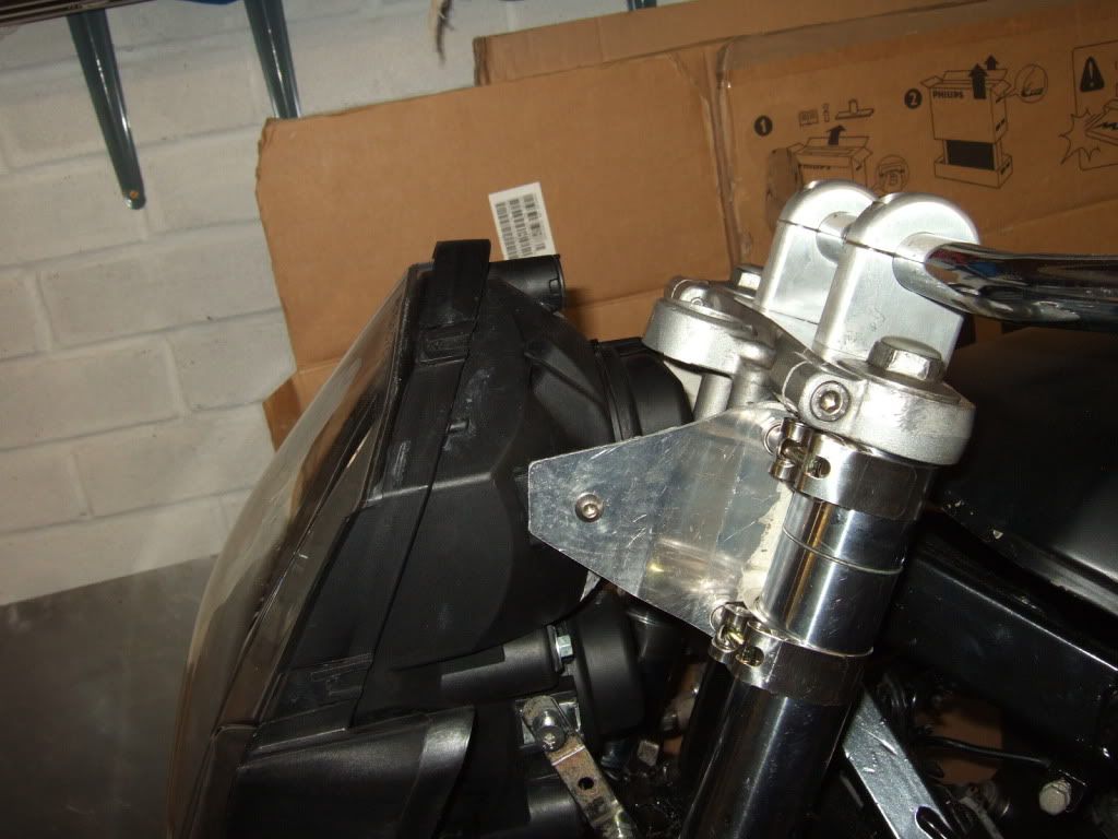
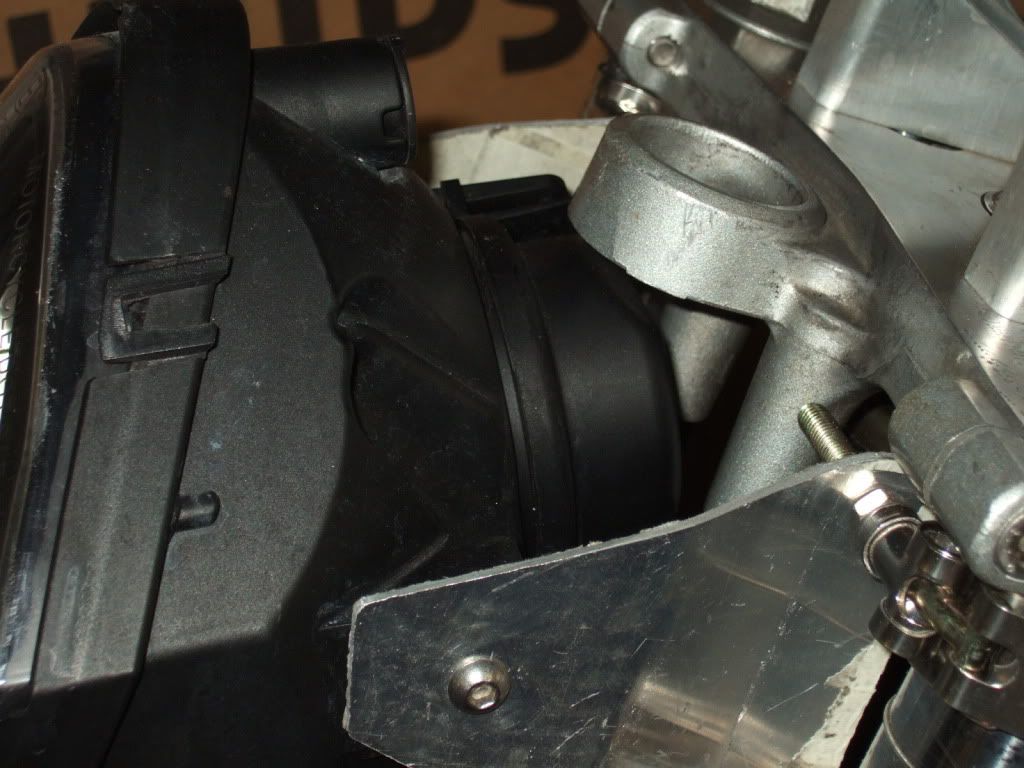
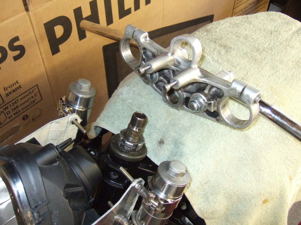
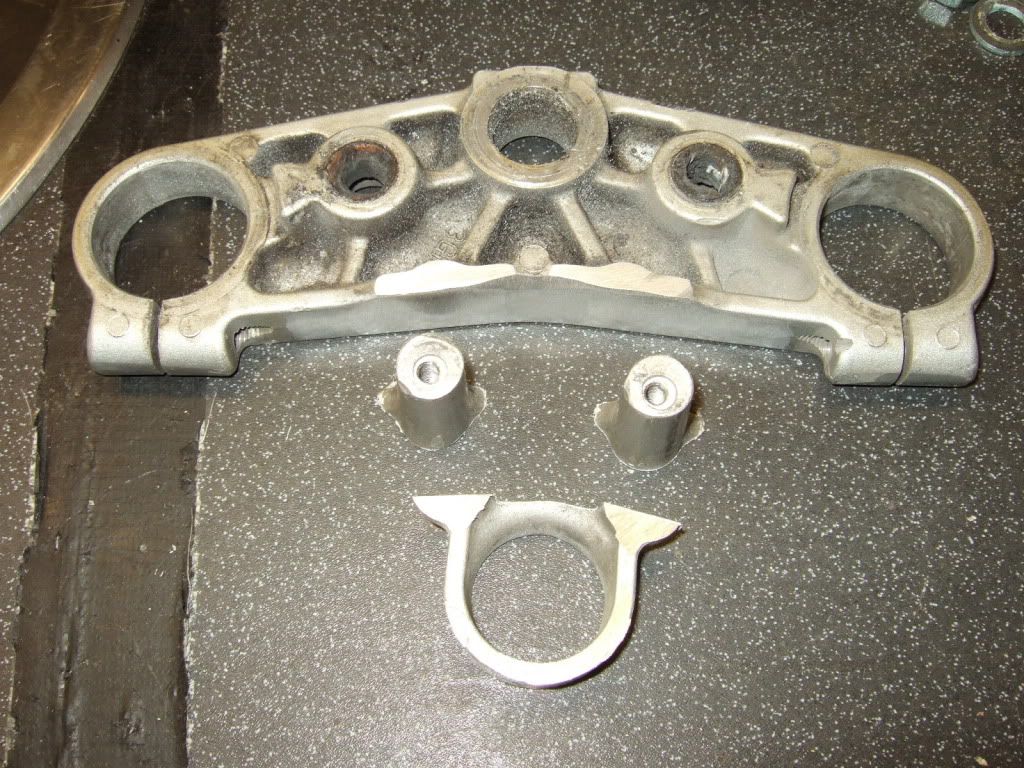
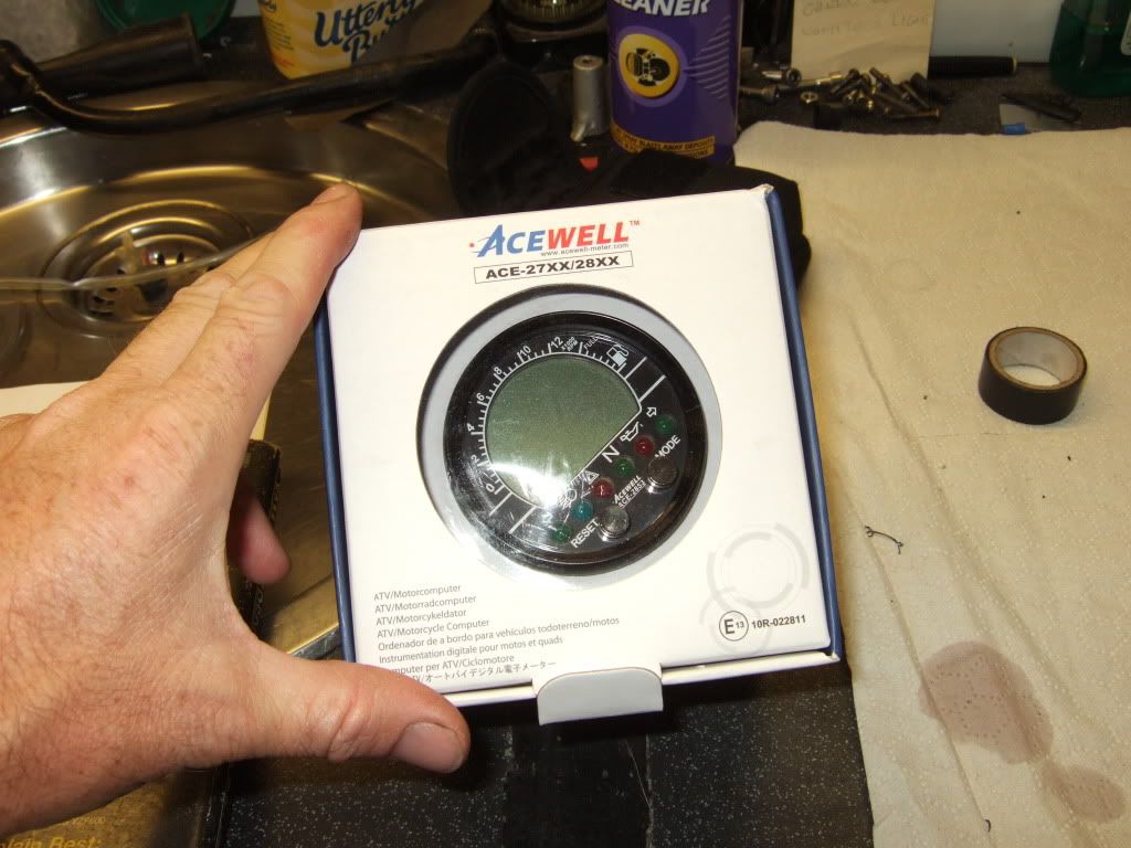
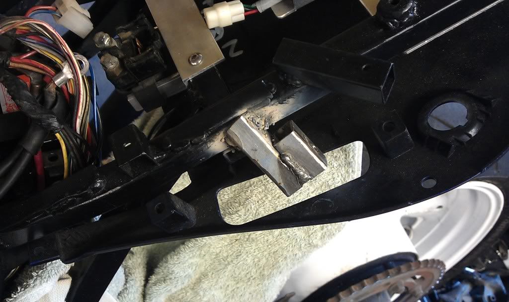
To make room for the Acewell speedo that I've got coming and to allow the headlight to fit a little closer to the forks I had to take the step of cutting the ignition lock mounting off of the top yoke.
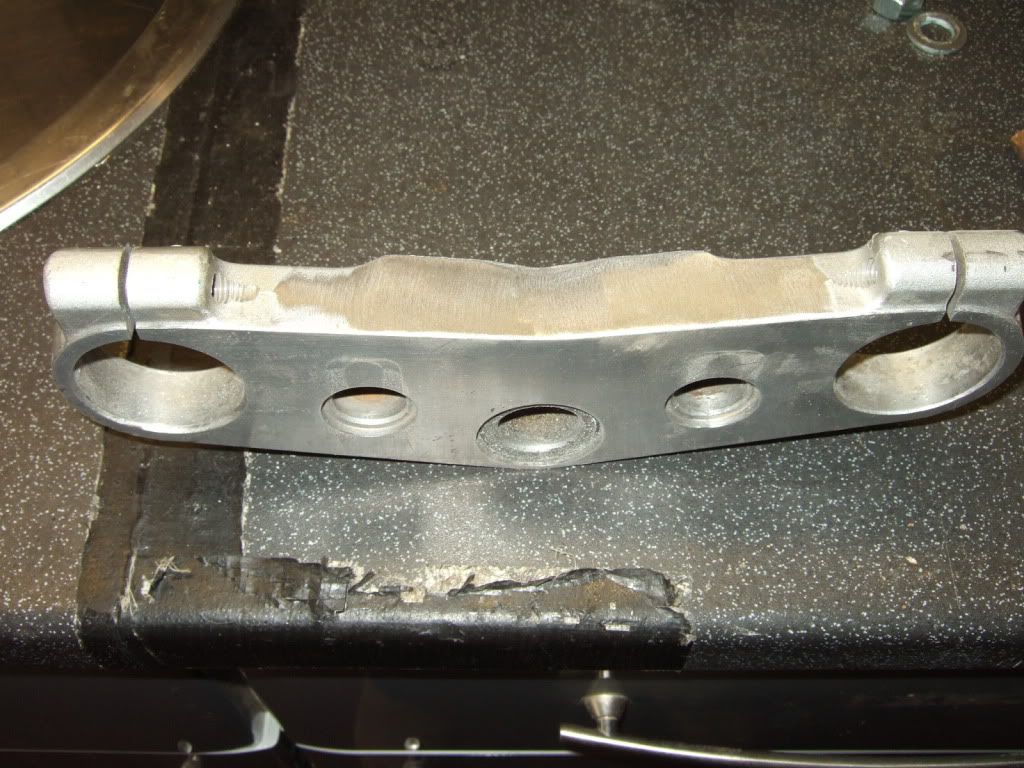
Image

Image

Image

Job done!

Image

Image

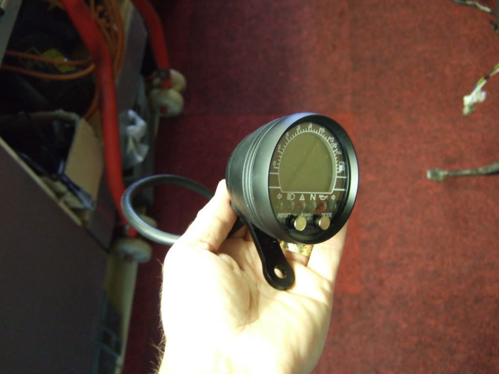
New brackets will be manufactured once speedo arrives for a closer fit.

Image

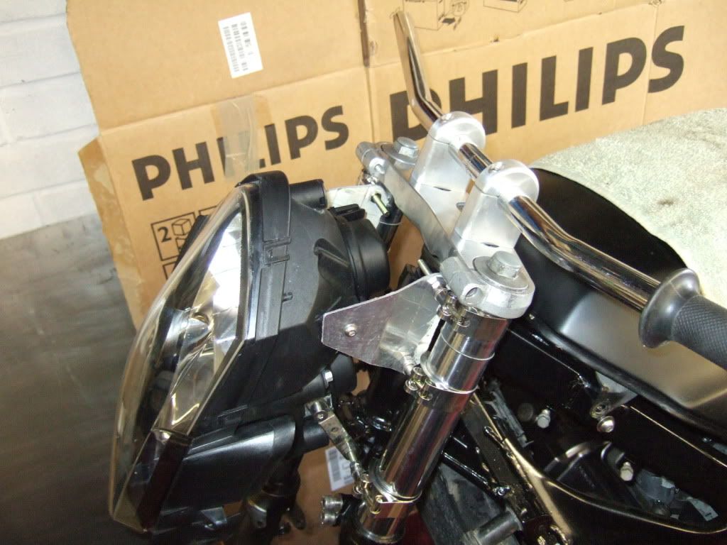
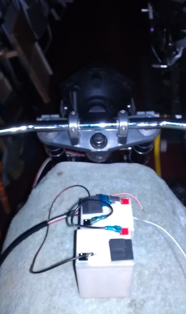
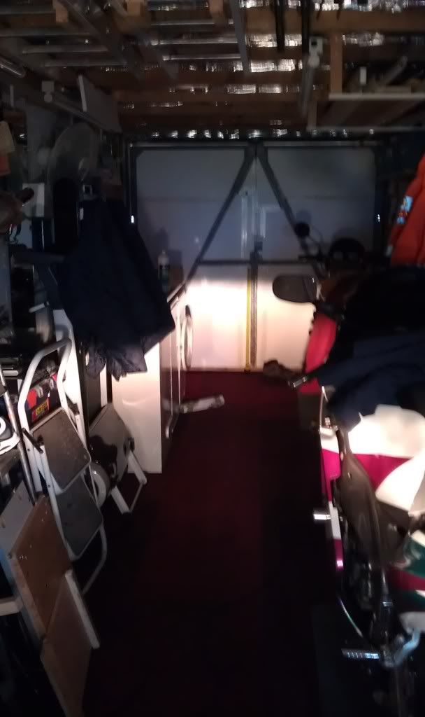
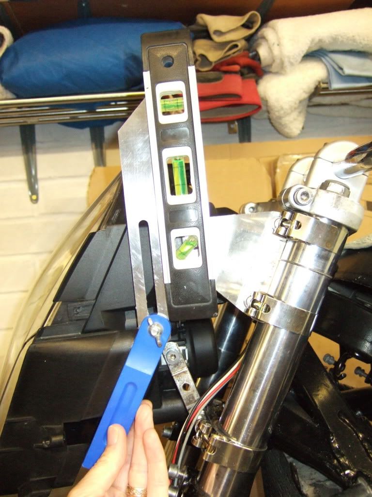
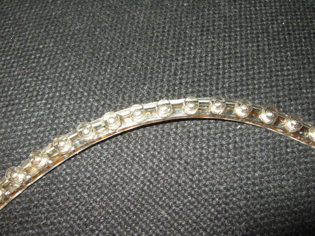
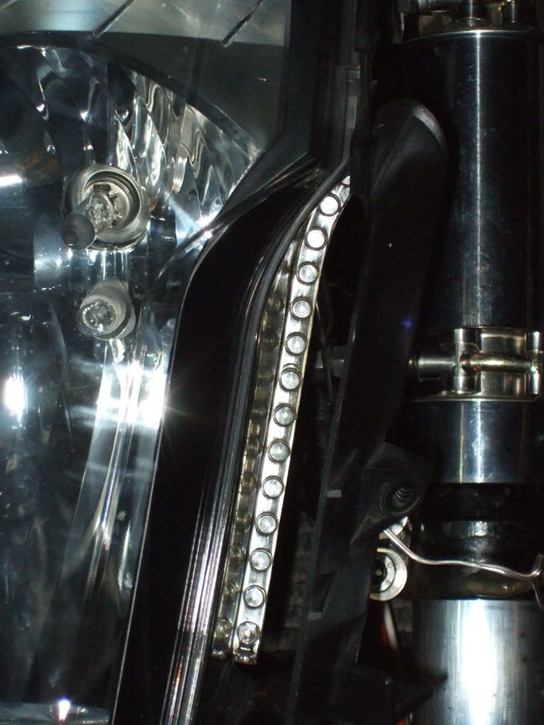
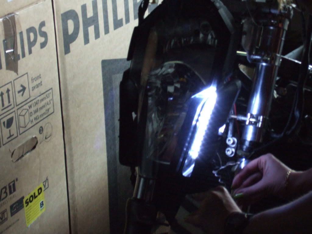
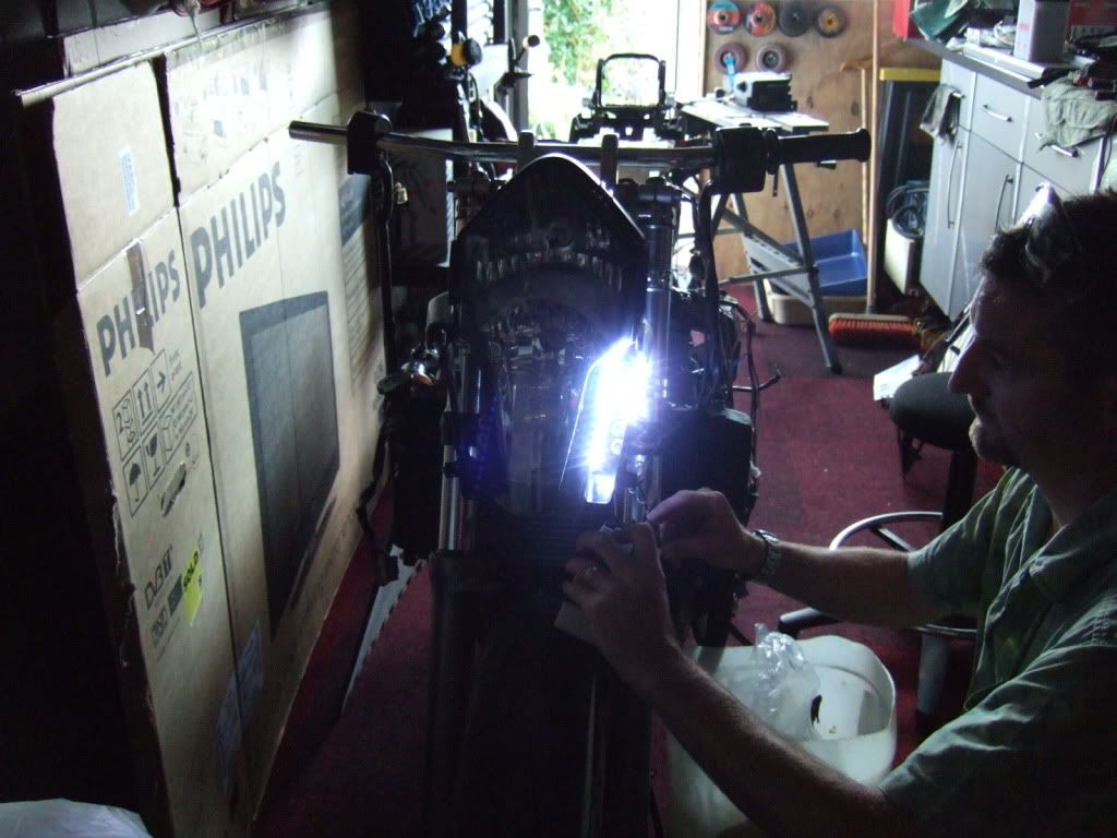
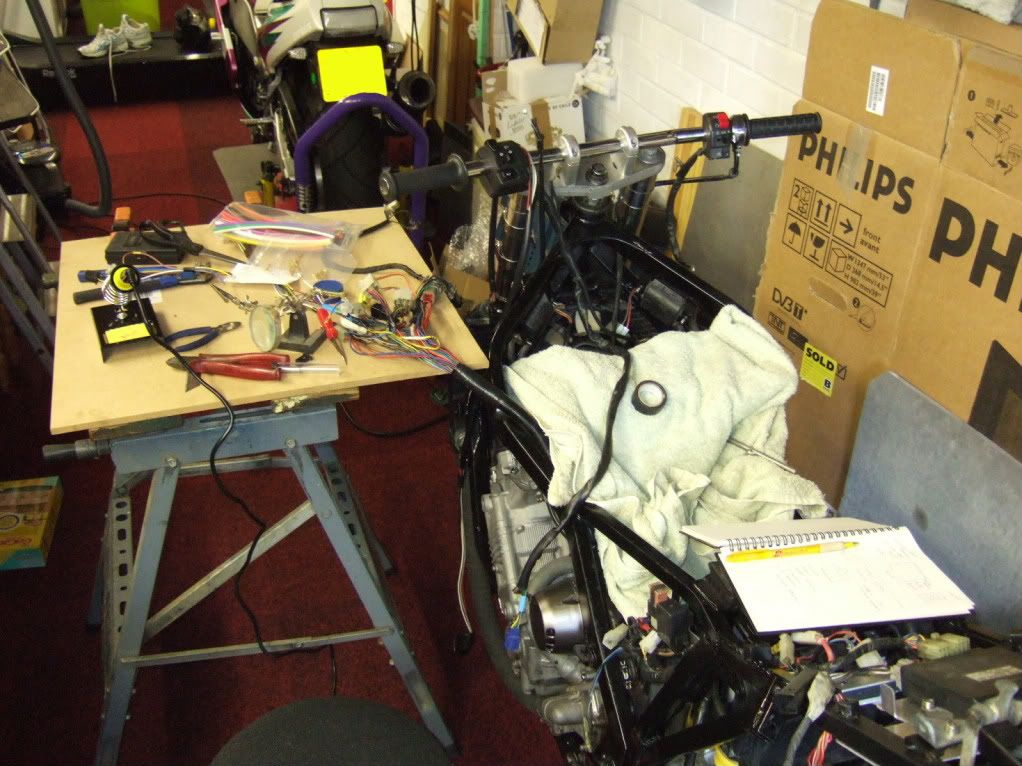
that done I made my headlight wiring loom and rigged it up to a temporary battery to get the headlight aim somewhere near where it needs to be.

Image

Image

Image

Image

Image

Then took a reading so I know what sort of position it needs to be in once the new brackets are made.
(the camera was on the piss when the photo was taken :D )

Image

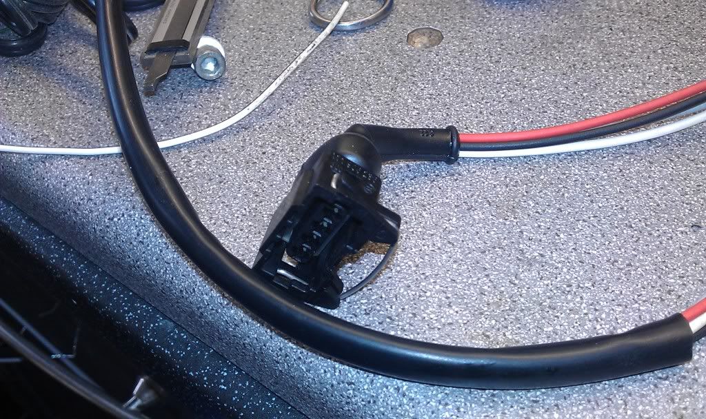
Now that the headlight aim is sorted its time I set about sorting the wiring out.

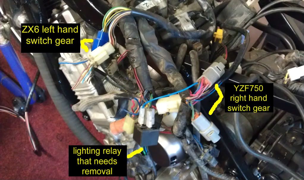
The previous owner never had any left hand switch gear, only the right side which consists of kill switch, starter and lights (off, side and main)
Now they had been wired up so that the light switch controls dip and high beam via a relay! so side lights is dip and main lights is high beam!!!
I wonder how many times he went from high beam to lights off by mistake :eek:

Any how I have a left hand switch cluster from a zx6 to put on so it may be some time to my next update as the wiring could cause brain fade!!

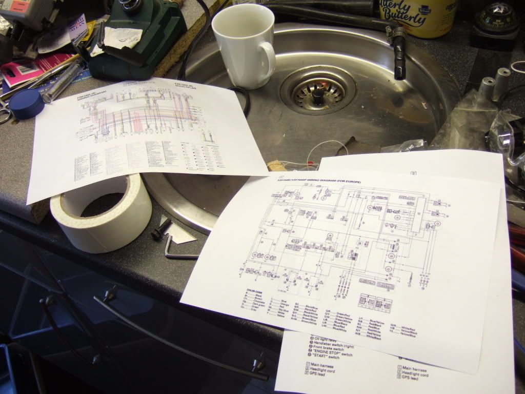
(yzf750 wiring loom grafted onto fzr1000 exup components,cdi relays etc, and also FZ750 clocks and tank sender)

Image

Image

Image

Image

my brain hurts just typing this update :lol:
Never Ever Bloody Anything Ever!!!
User avatar
mogster
Scooter Boy
Scooter Boy
Posts: 69
Joined: Tue May 13, 2008 10:32 am
Location: Manningtree

Post by mogster »

I got these there only cheap and work well

connectors
User avatar
fang
Pit-lane Reporter
Pit-lane Reporter
Posts: 741
Joined: Mon Jun 19, 2006 5:38 pm
Location: Bootiful Norfolk

Post by fang »

mogster wrote:I got these there only cheap and work well

connectors
Yep, had a look about on eBay and found these, every penny counts. :lol:

cheaper connectors

Shame they don't come in different colours so got some coloured heat shrink to differentiate connector blocks. :D
Never Ever Bloody Anything Ever!!!
User avatar
fang
Pit-lane Reporter
Pit-lane Reporter
Posts: 741
Joined: Mon Jun 19, 2006 5:38 pm
Location: Bootiful Norfolk

Post by fang »

well, I have spent the last 2 days slowly working through the wiring and have managed to install the left hand switch gear that was missing and remove the relay set up that the previous owner had substituted in its place.

Image

Also managed to route out the indicator wiring and have that connected in (on a temp basis as waiting for proper connectors)
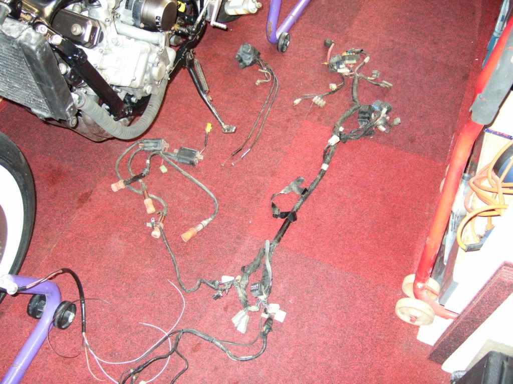
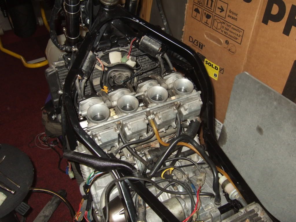
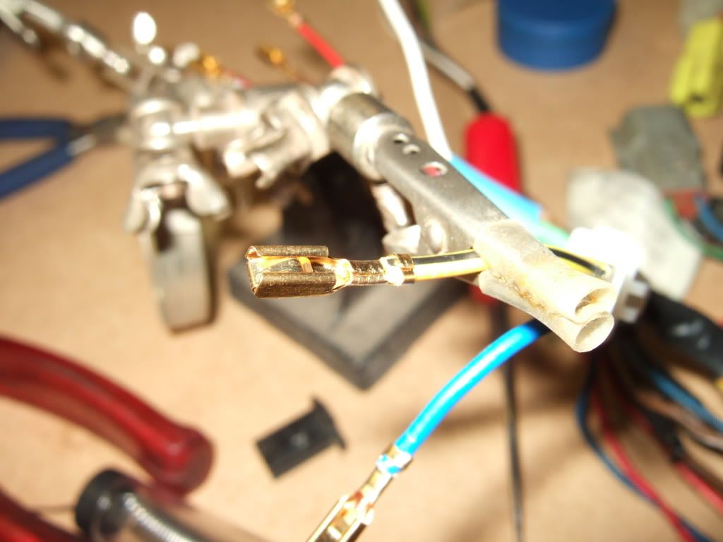
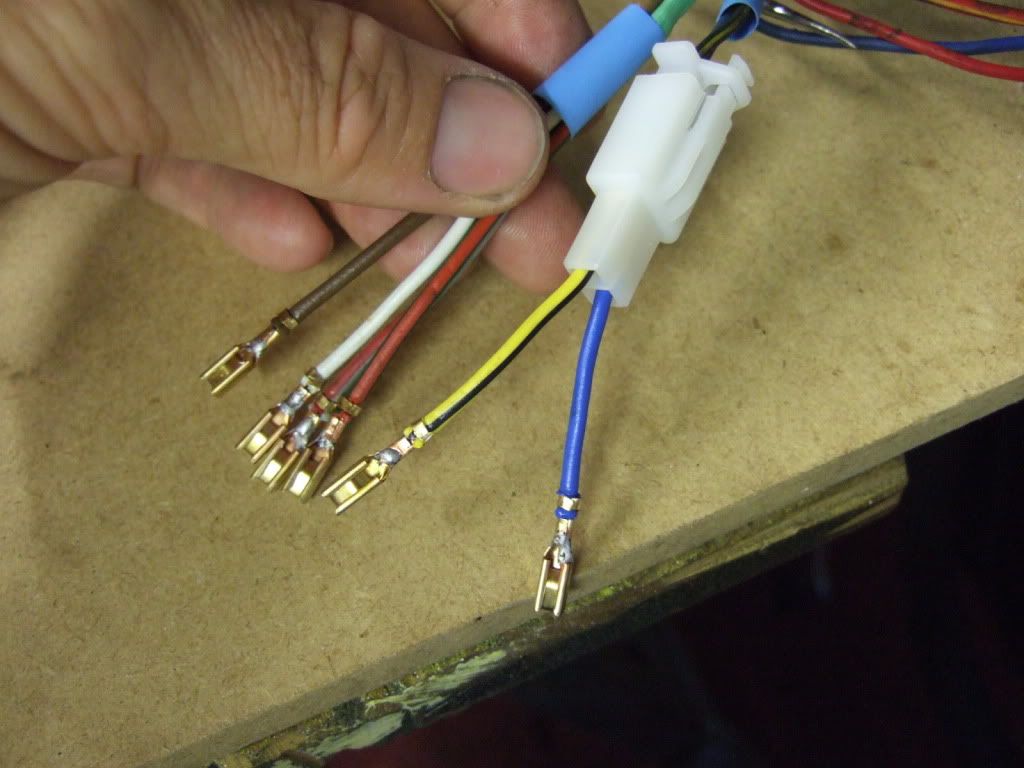
once all these were found and checked off came the loom for a bit of soldering

Image

Image

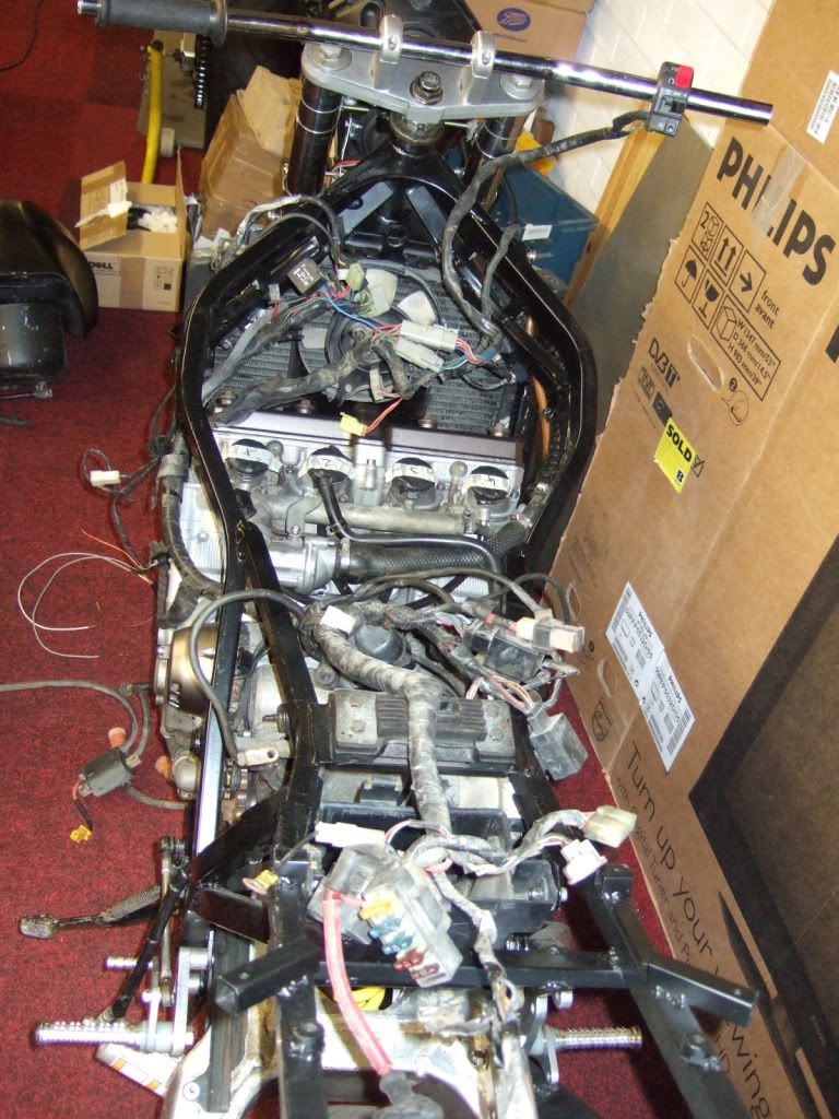
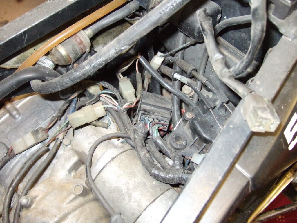
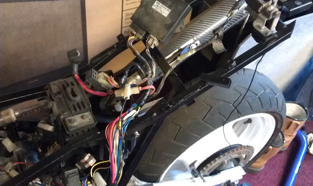
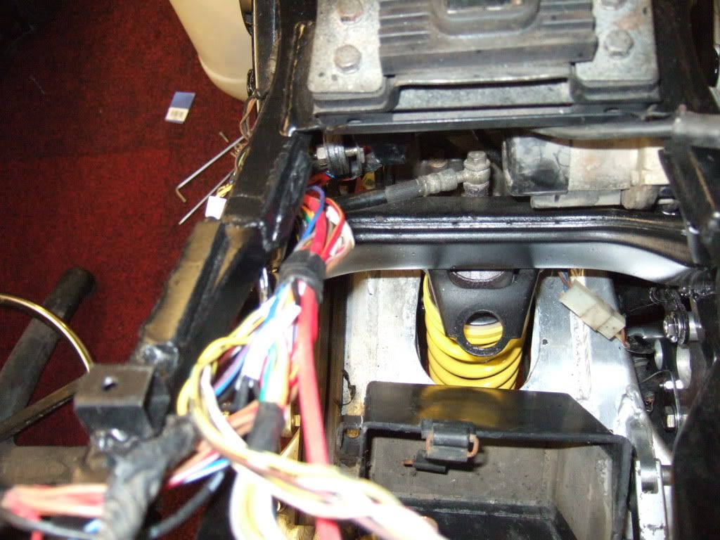
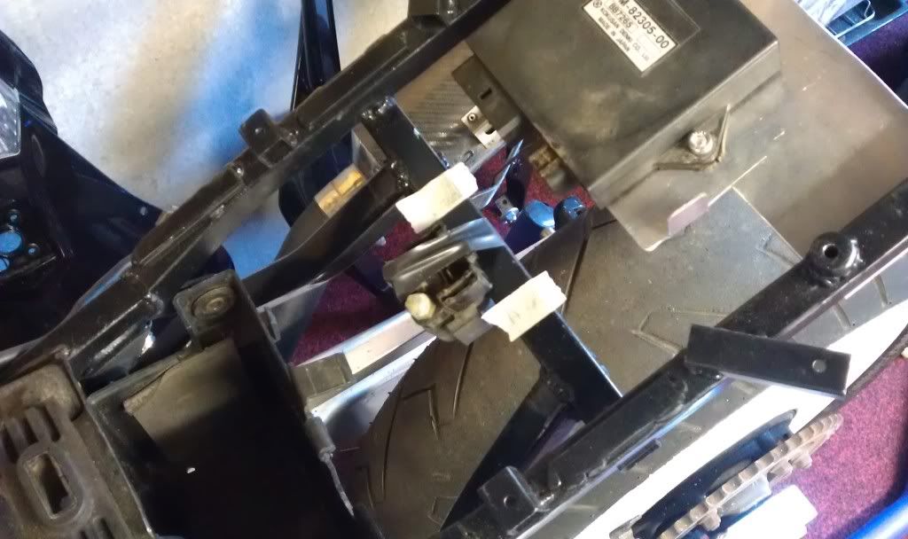
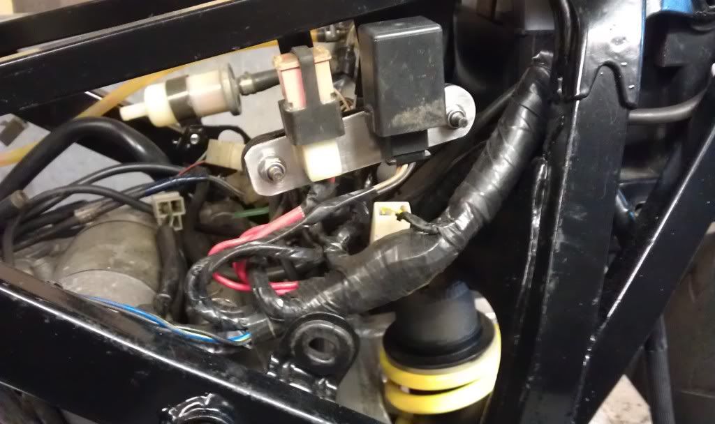
once that was done the loom was stripped back a bit more to see if I could remount bits in alternate places, ( I say remount but they were originally just left laying between the engine and swingarm)
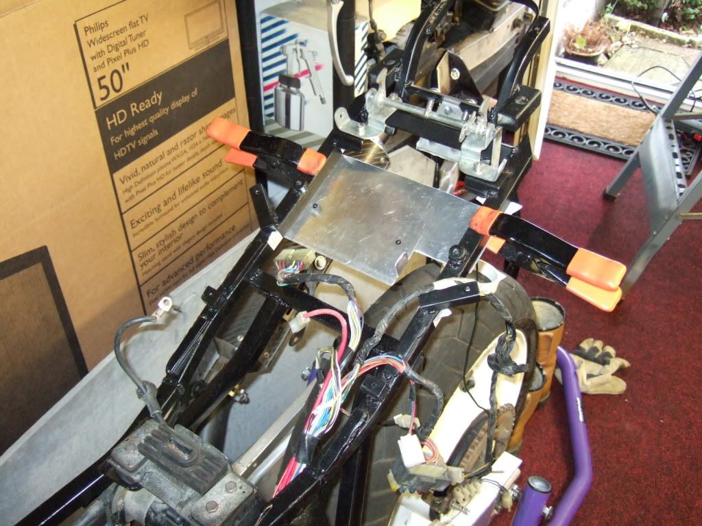
As they were

Image

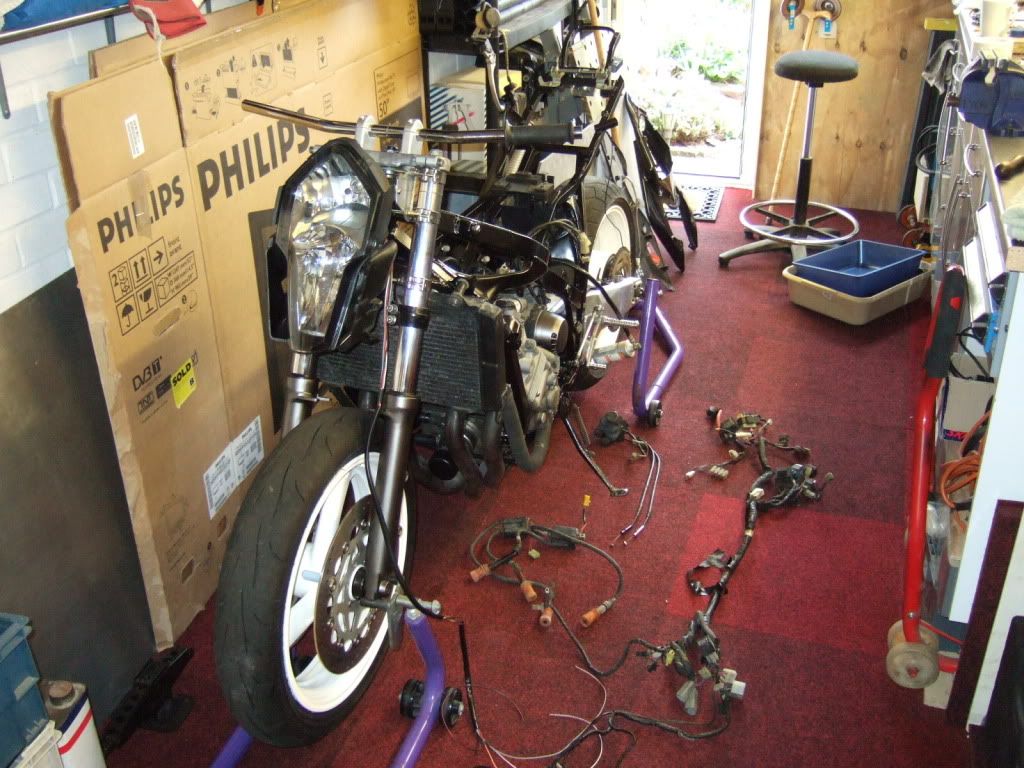
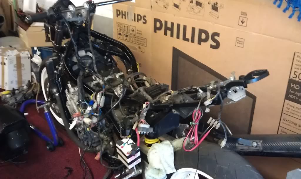
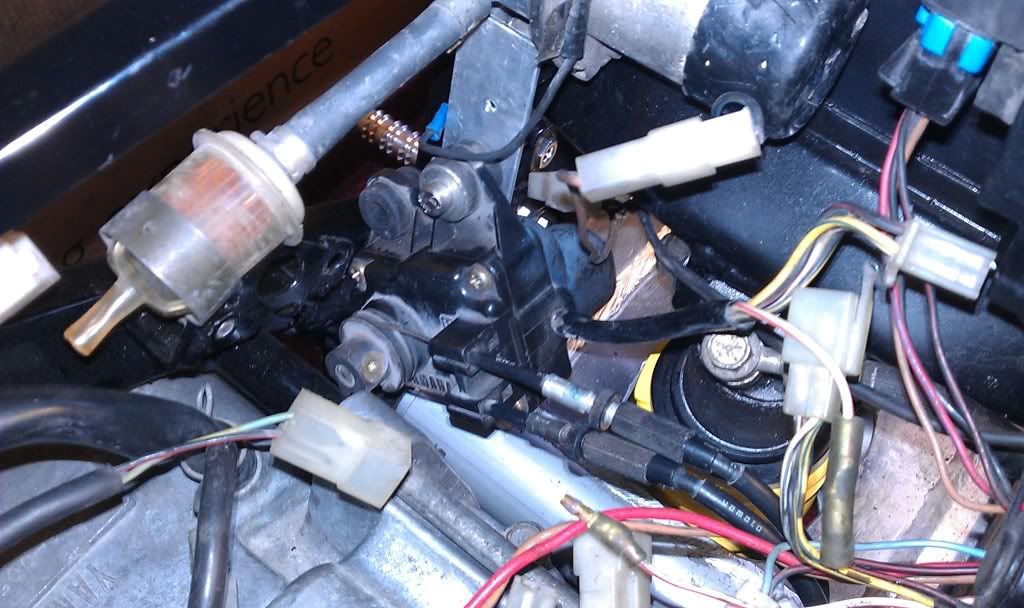
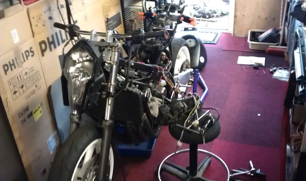
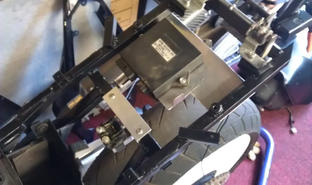
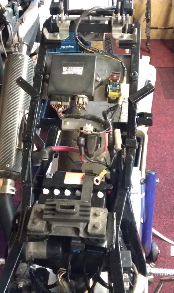
As they will be, servo mounted on temp bracket and locations found for relays,

Image

Image

Image

Just need to mount a plate under the subframe for the CDI and that'll be that, bar any tidying up afterwards.

Image

can only handle a bit at a time so thats it for today.. :D
Never Ever Bloody Anything Ever!!!
User avatar
nuggitt
Moderator
Moderator
Posts: 5968
Joined: Fri May 22, 2009 9:45 pm
Location: North Yorkshire

Post by nuggitt »

I'm not surprised mate. :nod:

Spaghetti junction or what!!! :eek: :eek:
Bit of advice. Buy a good bed and a good pair of shoes, because if you aren't in one you'll be in the other.
User avatar
fang
Pit-lane Reporter
Pit-lane Reporter
Posts: 741
Joined: Mon Jun 19, 2006 5:38 pm
Location: Bootiful Norfolk

Post by fang »

A little more done,

My Audi style LED side lights arrived.

Image

Which will be installed inside the scoops either side of the headlight.

Image

Image

Image

Made a plate to mount the CDI and fuse box to

Image

Then cut out the side of the battery box so the loom can be routed without crushing it.

Image

Image

Image

Image

My speedo arrived, ready for installation.

Image

Image

Reinstalled the carbs and decided I'd see if she runs before I wrap the loom up only to discover a problem afterwards.

Image

Image

Image
Never Ever Bloody Anything Ever!!!
User avatar
fang
Pit-lane Reporter
Pit-lane Reporter
Posts: 741
Joined: Mon Jun 19, 2006 5:38 pm
Location: Bootiful Norfolk

Post by fang »

final pic above is actually a vid

hit submit instead of preview.............doh

Video below

Image

But she lives again, actually sounds better than my Exup.... which is upsetting :crybaby:
Never Ever Bloody Anything Ever!!!
User avatar
nuggitt
Moderator
Moderator
Posts: 5968
Joined: Fri May 22, 2009 9:45 pm
Location: North Yorkshire

Post by nuggitt »

Looking good and sounding very nice. :nod: :nod:
Bit of advice. Buy a good bed and a good pair of shoes, because if you aren't in one you'll be in the other.
User avatar
fang
Pit-lane Reporter
Pit-lane Reporter
Posts: 741
Joined: Mon Jun 19, 2006 5:38 pm
Location: Bootiful Norfolk

Post by fang »

Righty ho, heres whats been going on since the in house (garage :lol: ) testing.

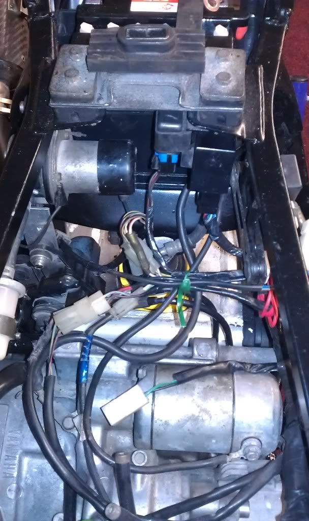
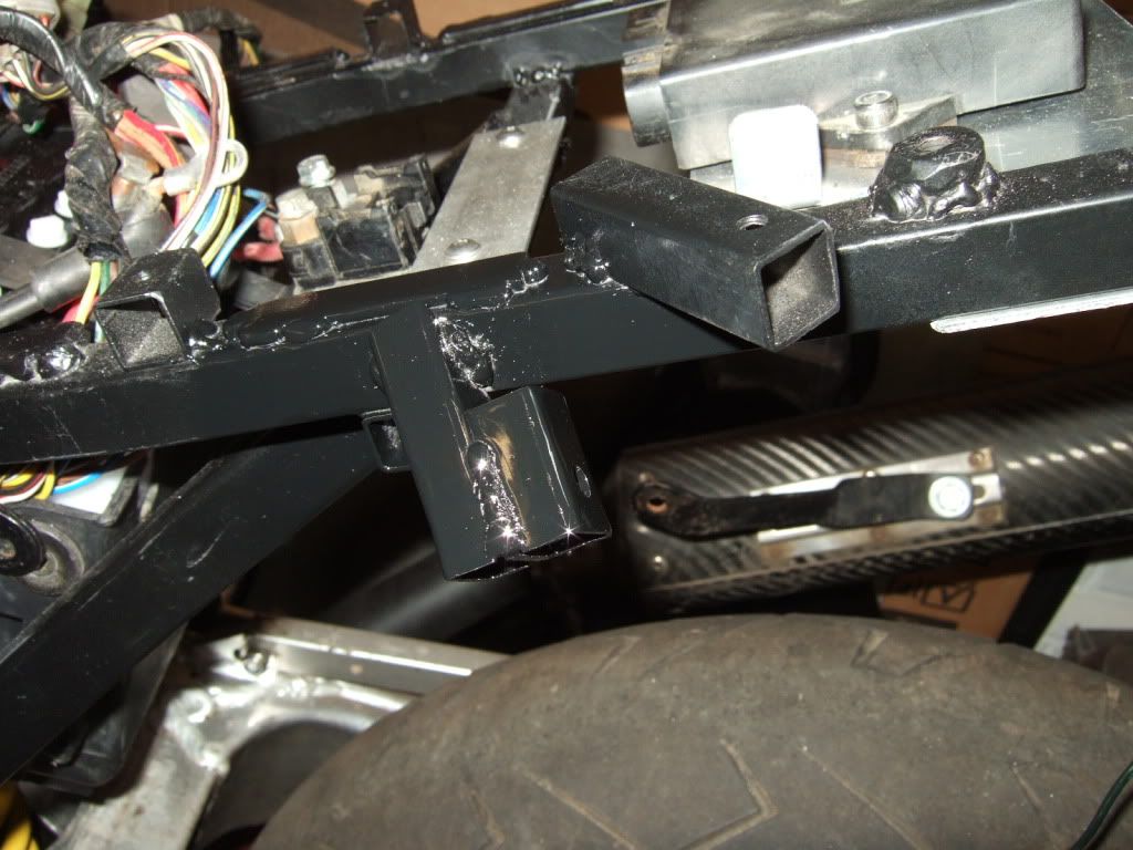
finalised fixing the CDI plate then set about mounting the starter solenoid.

Image


Solenoid test mounted with tape to make sure cables reach.

Image

Image

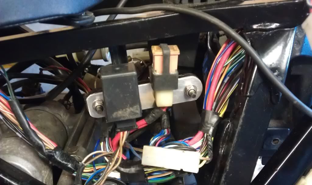
manufactured a bracket to hold main fuse and indicator relay.

Image

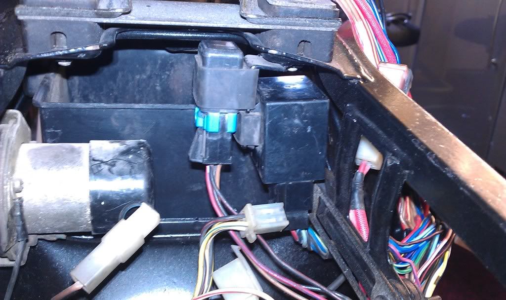
And wrapped the rear of the loom back up so its now all nice and tidy. just waiting for a few items to come from Fleabay to connect the rear light and indicators.

A lot tidier than it was
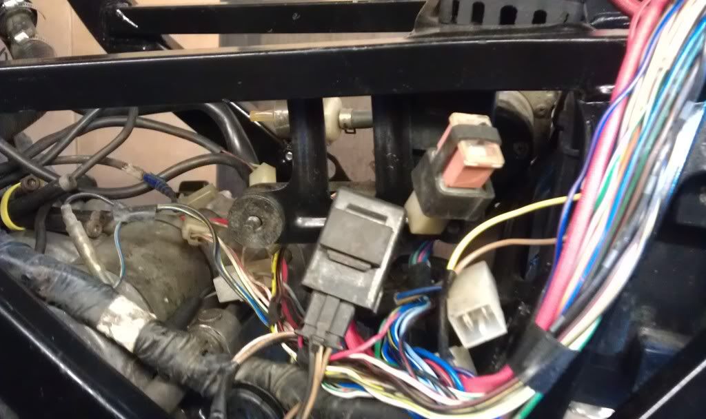
 :D
Then

Image

Now

Image

Image

Image


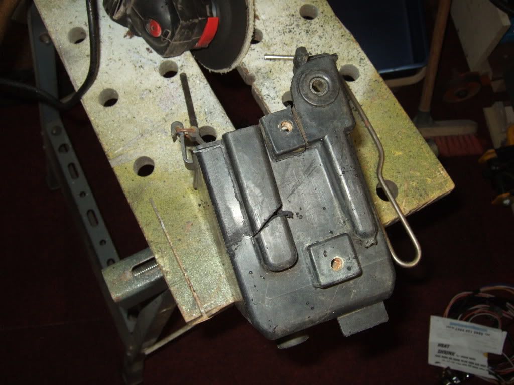
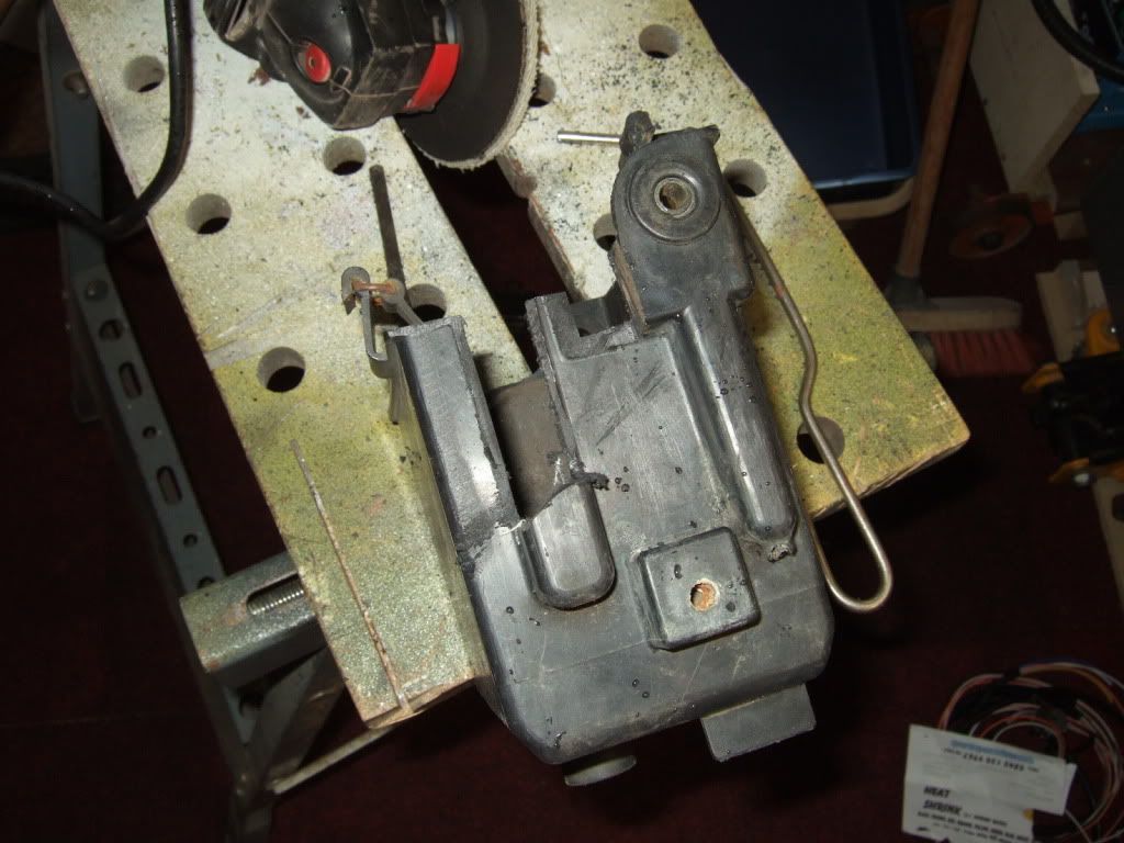
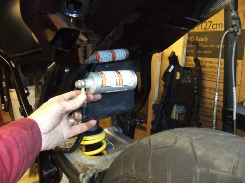
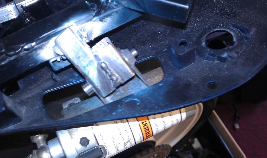
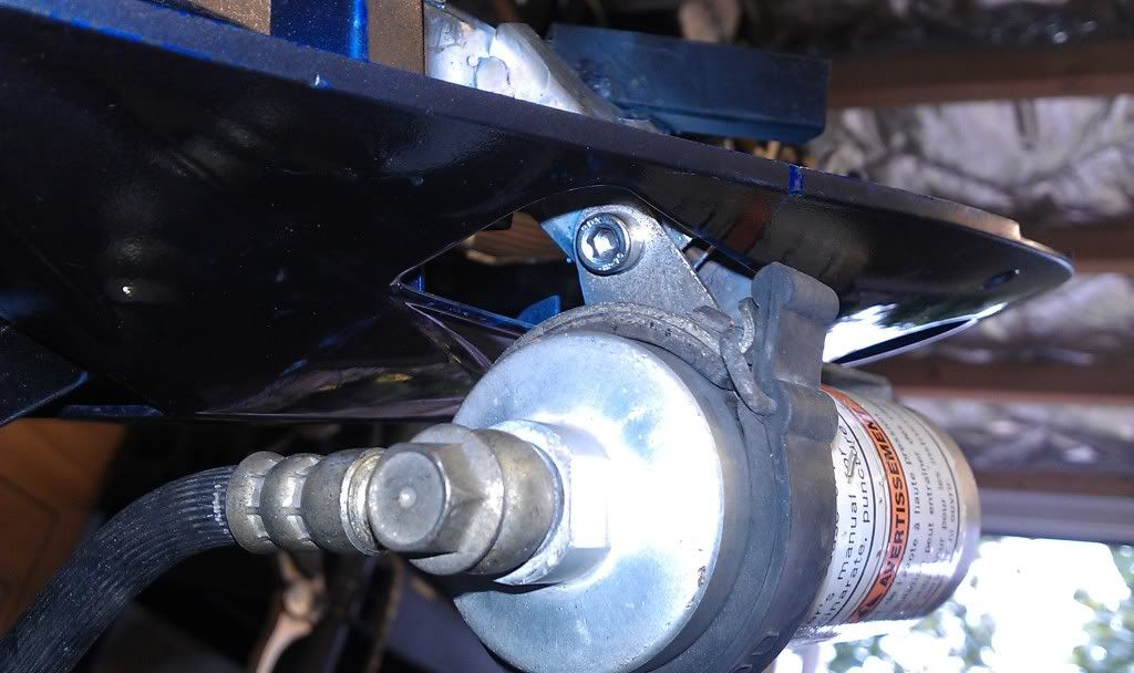
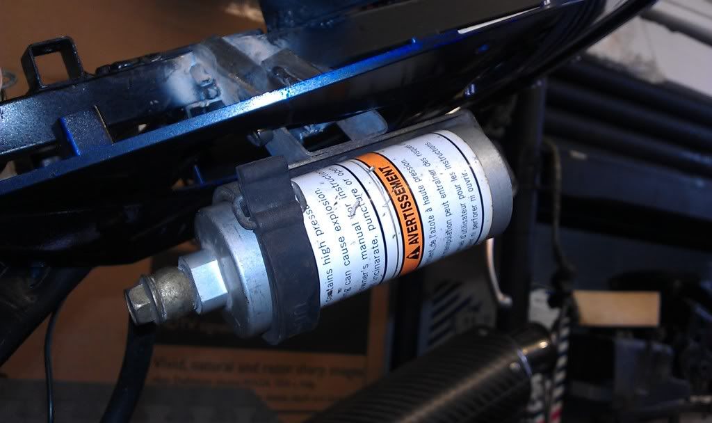
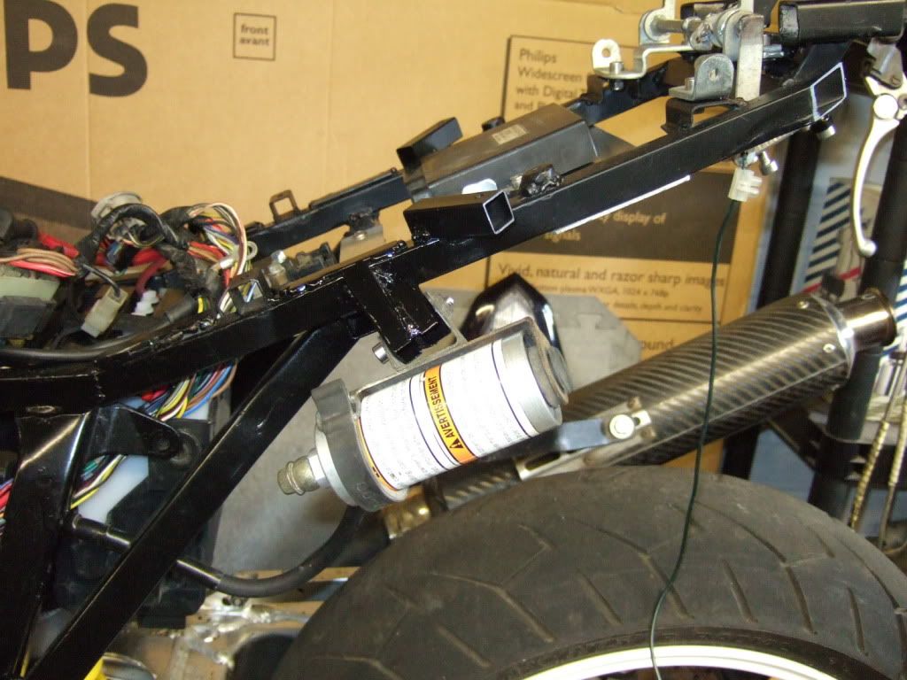
Now if you may remember I was toying with the idea of mounting the Shock reservoir from the battery box.

Image

Well, decided against that, instead I have mounted it via a bracket through the hole in the undertray that the R6 rear pegs mount.

Image

Image

and it doesn't hinder removal as the mounting bolt is angled so the reservoir can be removed easily.

Image

Image

Image

Image

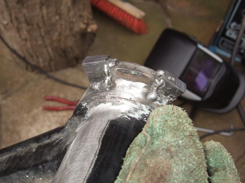
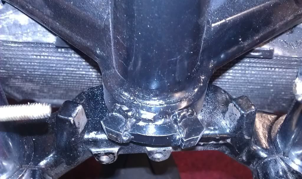
Whilst I was at it I also "adjusted" the steering lock stops now that the rad is fitted to give me more lock, just need to take her outside again to check the turning circle, but its more than it was.

Image

Image

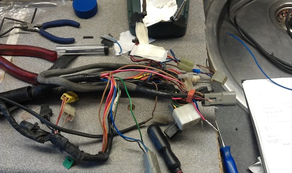
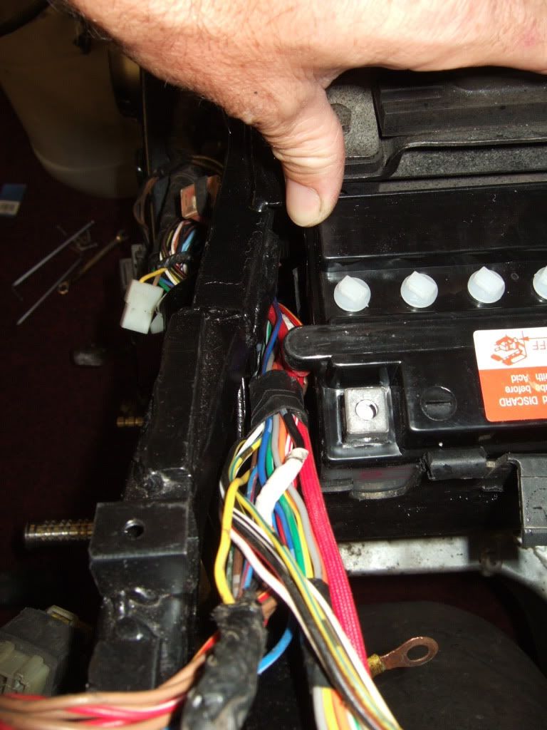
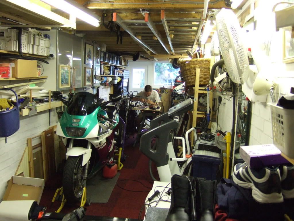
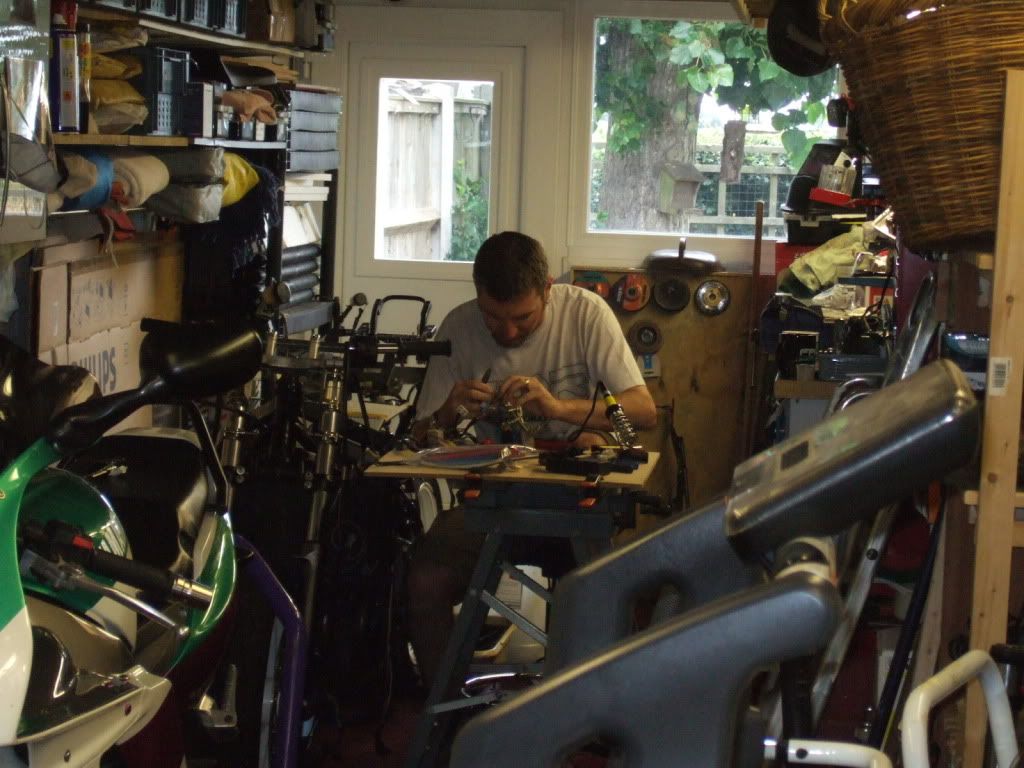
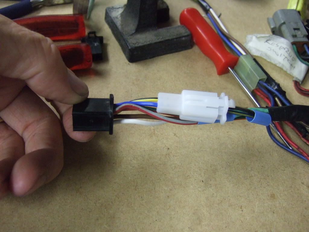
Next up was sorting out the front half of the wiring loom.
Lisa snuck a photo whilst I was concentrating.

Image

Image

Anyhow, workmate utilised as a makeshift solder station!!

Image

New connections made for switch gear.
Image

Image

Image

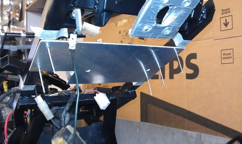
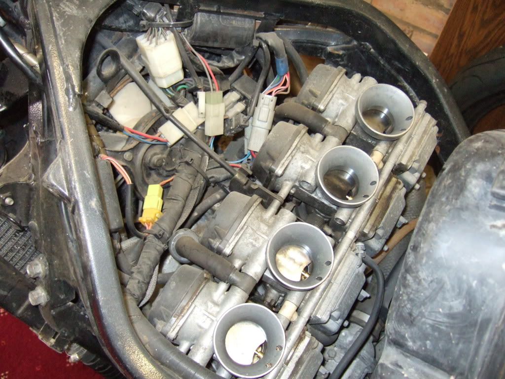
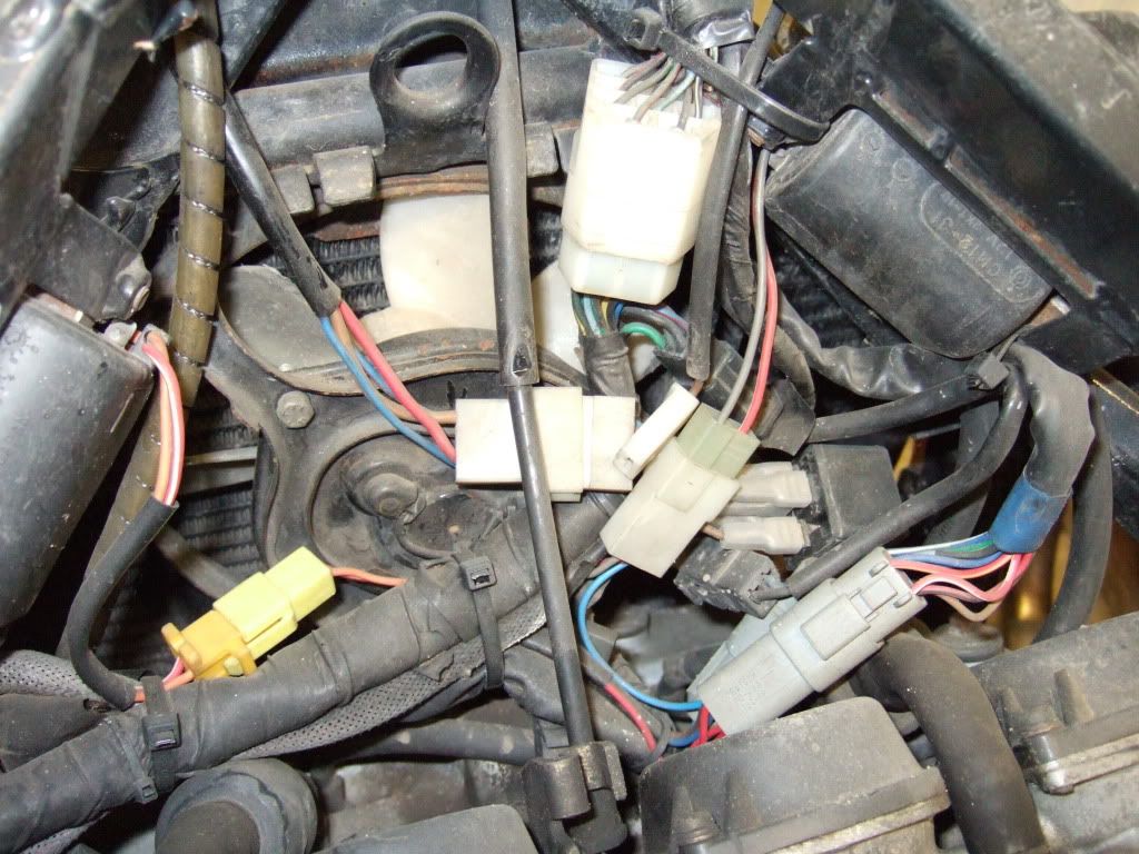
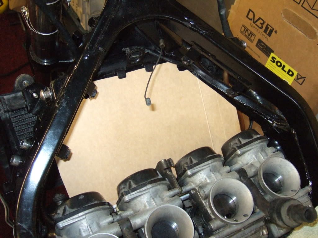
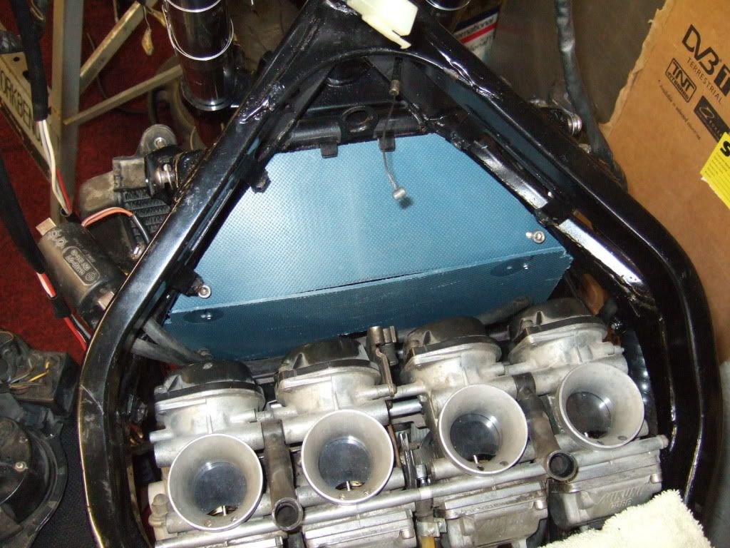
Once that was done I set about making a trough for the electrics to sit in.

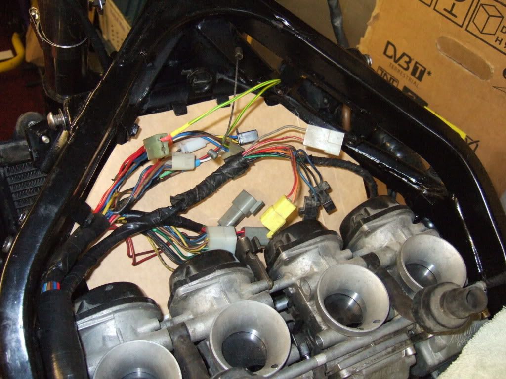
The previous owner had just crammed the electrics under the airbox but I want then to be a bit better protected with a shield between them and the radiator.

How it used to was

Image

Image

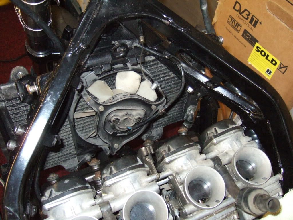
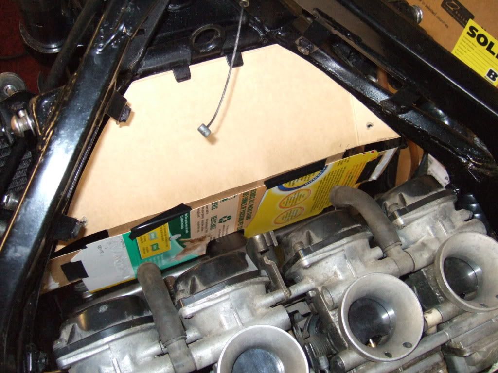
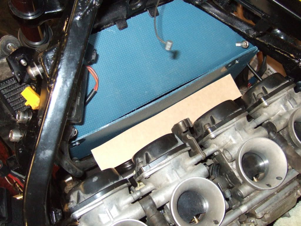
So set about making a template with card.

Image

Image

Image

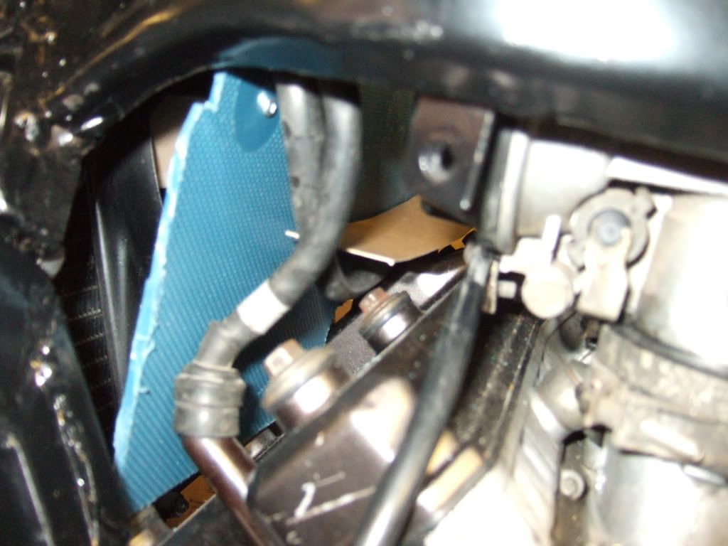
But once the airbox is fitted there is no room so I added a trough for the connectors to sit in.

Image

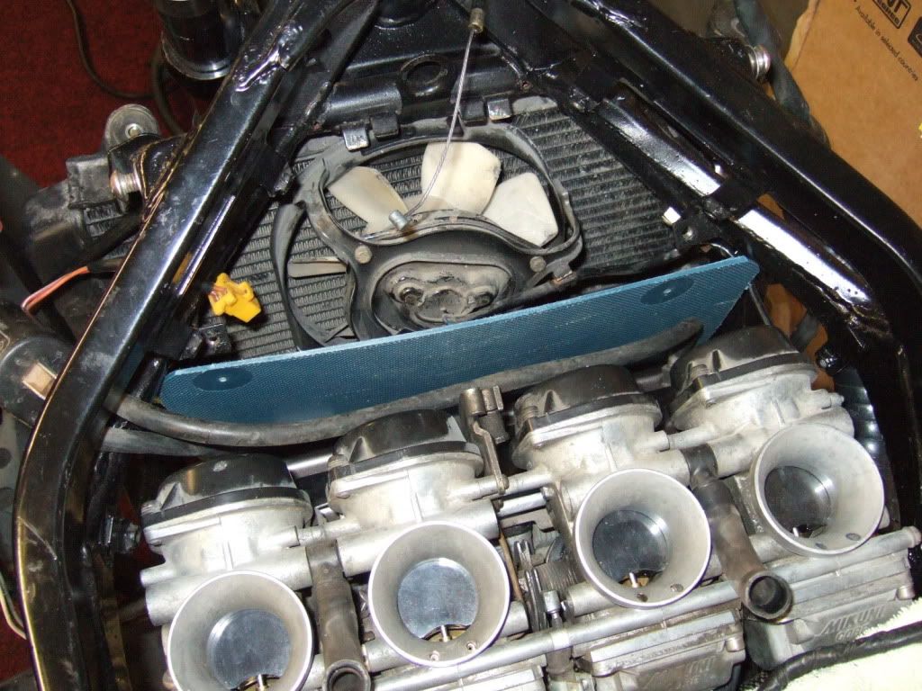
Then set about making one from plastic.


Image

Image

Will add a "shelf" for the connectors to sit on whilst allowing clearance for the HT leads underneath.

Image

Image

But this is as far as I've got today so I will resume tomorrow. :D
Never Ever Bloody Anything Ever!!!
User avatar
nuggitt
Moderator
Moderator
Posts: 5968
Joined: Fri May 22, 2009 9:45 pm
Location: North Yorkshire

Post by nuggitt »

Hats off to you mate. This is a fantastic thread. Loving every minute. :nod: :thumbsup:
Bit of advice. Buy a good bed and a good pair of shoes, because if you aren't in one you'll be in the other.
User avatar
oldskoolexup
Motormouth
Motormouth
Posts: 1219
Joined: Sun Jul 19, 2009 11:45 am
Location: THE place...some are born here, some drawn here...Manchester

Post by oldskoolexup »

Perhaps I've missed the detail but are you going to have protection for the connectors that go into CDI so spray from rear doesn't penetrate connections?
Life begins at the end of your comfort zone,
Learn from the mistakes of others.............................
You can't live long enough to make them all yourself
&
Carpe Diem - seize the moment. Don't dream... Do!
User avatar
fang
Pit-lane Reporter
Pit-lane Reporter
Posts: 741
Joined: Mon Jun 19, 2006 5:38 pm
Location: Bootiful Norfolk

Post by fang »

nuggitt wrote:Hats off to you mate. This is a fantastic thread. Loving every minute. :nod: :thumbsup:
Cheers Nuggitt, sometimes I think I may be waffling on too much and adding unnecessary detail, but Lisa reckons it keeps me quiet :D
Never Ever Bloody Anything Ever!!!
Post Reply