Fangs "new" toy!!

Post your pictures here: your bikes, meets you've attended, modifications you've made, x-rays you've had taken...
Post Reply
User avatar
fang
Pit-lane Reporter
Pit-lane Reporter
Posts: 741
Joined: Mon Jun 19, 2006 5:38 pm
Location: Bootiful Norfolk

Post by fang »

Right then, a little bit more progress.

More assorted Stainless bolts purcahsed.

Image

Replaced battery box cover bolts with domed items.

Image

Image

Then finished making my headlight sub loom and extending the front indicators

Image

Image

Image

Then set about checking the wiring for the speedo so I know whats what before final fix.

Image

Indicators

Image

Neutral

Image

Highbeam

Image

Oil light

Image

Even got the fuel Gauge to work, sender is lying on paperwork.

Float low = low fuel

Image

Float high = full tank

Image

After this success, yet to be wired permanently I started thinking about installing my side lights. Sparkplug boxes are purely to maintain shape of the curve so I can see what they look like lit.

Image

Image

Just got to find a way to get the strips to hold the curve, may try a bit of tubing or bend a strip of ally to the same contour of the shrouds.

Image

Image

That'll give me something to think about over a beer tonight.
Never Ever Bloody Anything Ever!!!
User avatar
fang
Pit-lane Reporter
Pit-lane Reporter
Posts: 741
Joined: Mon Jun 19, 2006 5:38 pm
Location: Bootiful Norfolk

Post by fang »

Gave it some thought, and before I drill any holes in the headlight to mount tubes or brackets I thought I'd have a go at sticking the strips in place with mastic.

The mastic was that thick it wouldn't squeeze down the spout, so squeezed it out like toothpaste and applied to LED strip with a knife, worked out a lot cleaner this way.

Just have to wait till tomorrow to see if it works then do the other side.

Image

Image

Image
Never Ever Bloody Anything Ever!!!
User avatar
nuggitt
Moderator
Moderator
Posts: 5967
Joined: Fri May 22, 2009 9:45 pm
Location: North Yorkshire

Post by nuggitt »

They've always said size matters.

I got a good tip from creed a while back. While you've got the float bowls off put some very fine emery on a plate of glass and rub the float bowls over the emery paper evenly a few times. :nod:
Bit of advice. Buy a good bed and a good pair of shoes, because if you aren't in one you'll be in the other.
User avatar
fang
Pit-lane Reporter
Pit-lane Reporter
Posts: 741
Joined: Mon Jun 19, 2006 5:38 pm
Location: Bootiful Norfolk

Post by fang »

nuggitt wrote:They've always said size matters.

I got a good tip from creed a while back. While you've got the float bowls off put some very fine emery on a plate of glass and rub the float bowls over the emery paper evenly a few times. :nod:
Yep, thats similar to how I "skimmed" the jet holders :unibrow:

Image
Never Ever Bloody Anything Ever!!!
User avatar
fang
Pit-lane Reporter
Pit-lane Reporter
Posts: 741
Joined: Mon Jun 19, 2006 5:38 pm
Location: Bootiful Norfolk

Post by fang »

Right, now that I could run the beast without it oozing petrol all over the place I set about trying once and for all to sort out the electronic reserve side of the system.

The way it works is as follows.
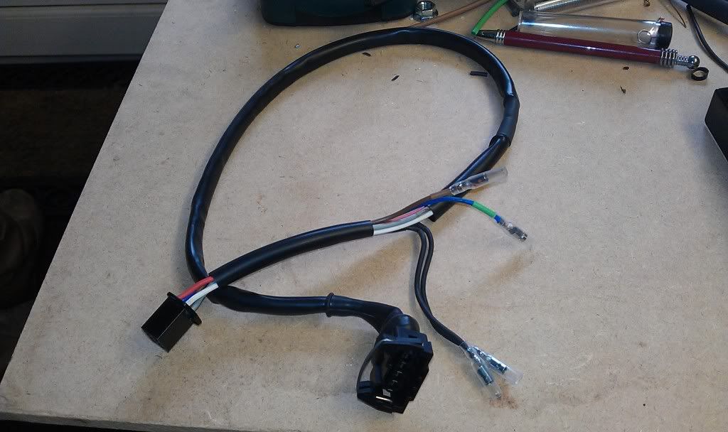
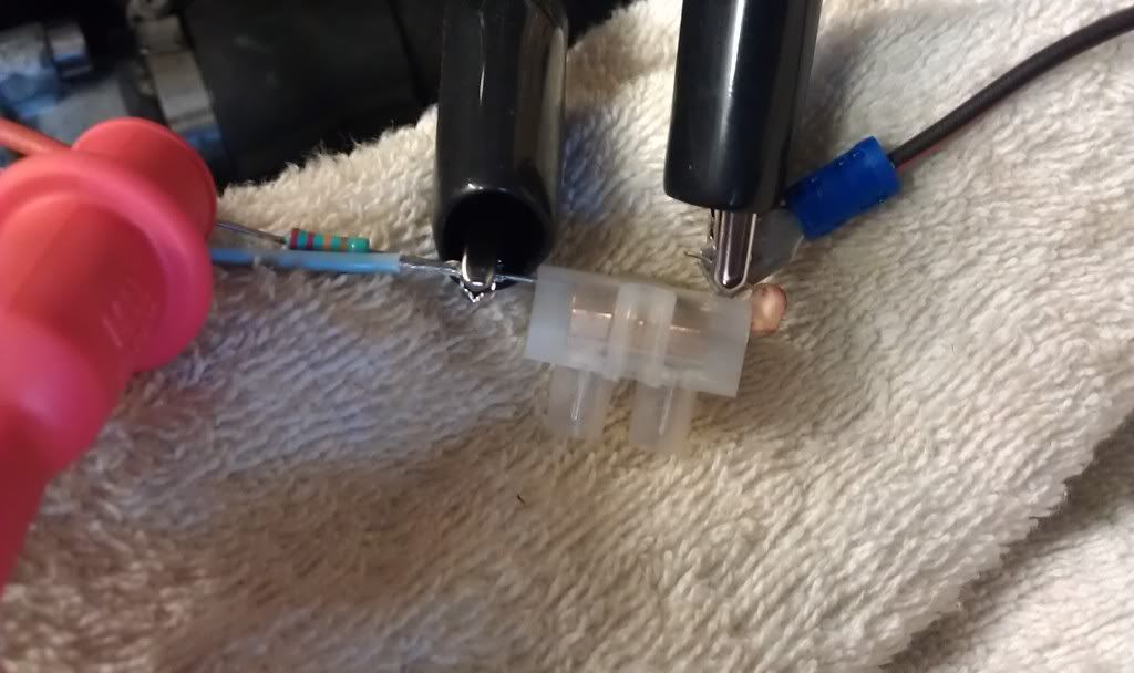
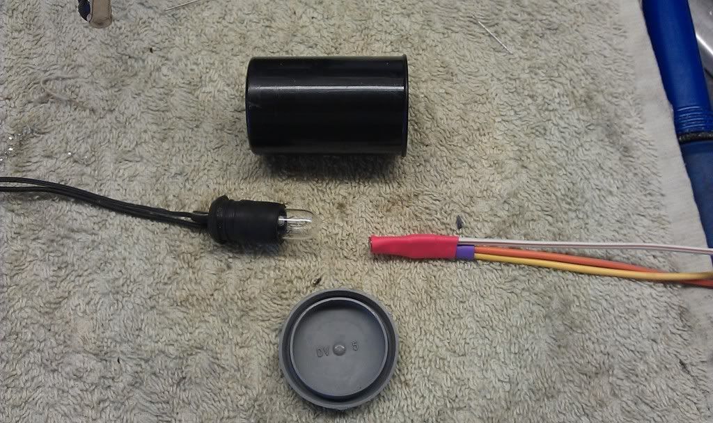
There is a sensor (thermistor) in the tank, when it is covered by fuel it's kept cool so has low resistance and 11v flows along the attached wire (Green White)

At one end of this wire is the pump control relay and at the other is a fuel level light.
The light is connected between the Green and white wire and a switched live.

So when fuel covers the sensor there is a voltage difference across the bulb of 1v, so not enough to illuminate it.

But as the fuel level drops and the sensor is exposed to air it heats up, thereby increasing its resistance and causing the voltage in the green white wire to drop from 11v to 3.8v which in turn increases the voltage differance across the bulb, causing it to illuminate.

This voltage drop is also sensed by the pump relay which cuts the power to the pump until the reserve switch is operated (switch is open for ON position and closed/connected for RES)

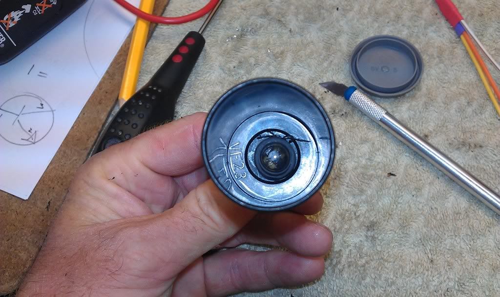
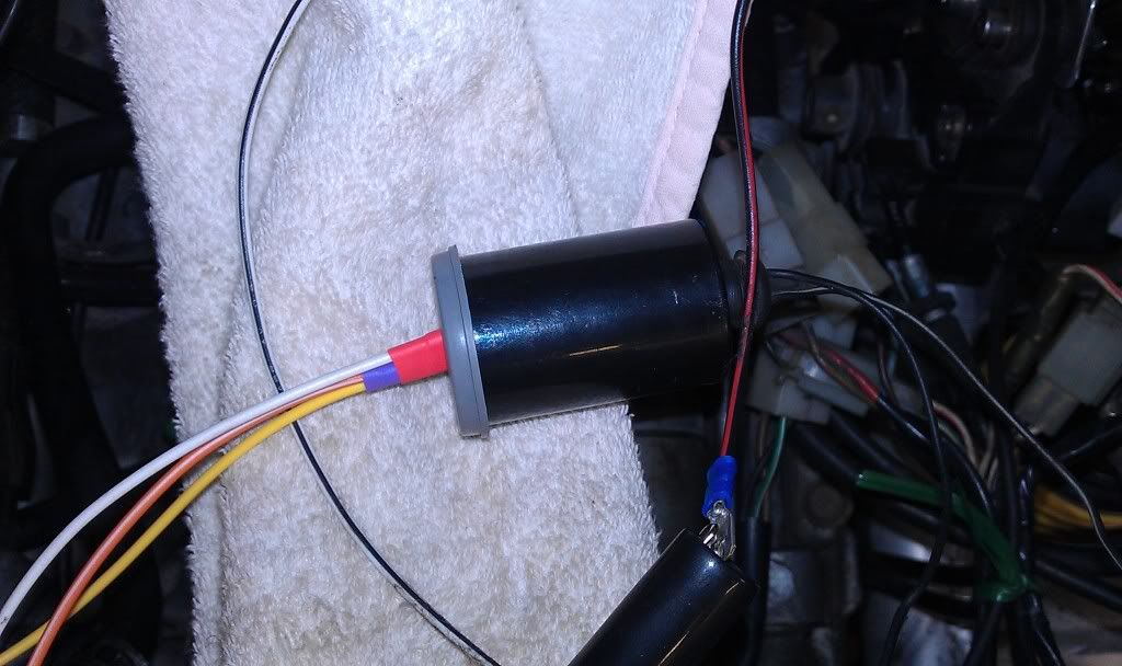
This was the theory, but as the previous owner had fudged the wiring to the tank and the sensor was duff (open circuit) the only way I could test this was to use the sensor from my Exup.

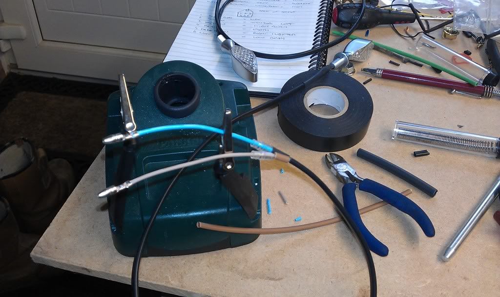
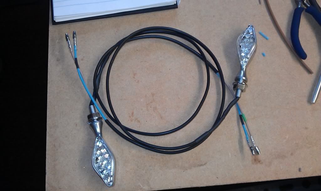
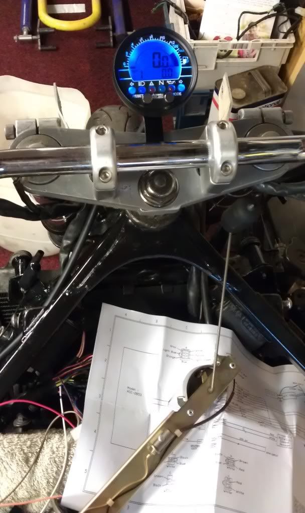
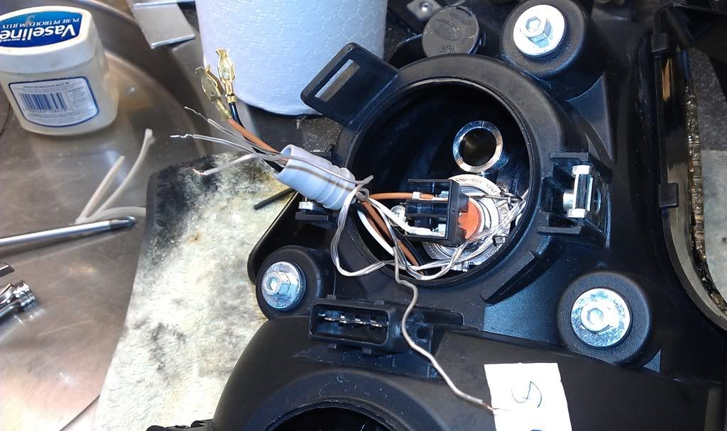
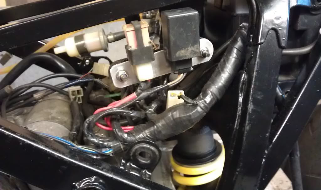
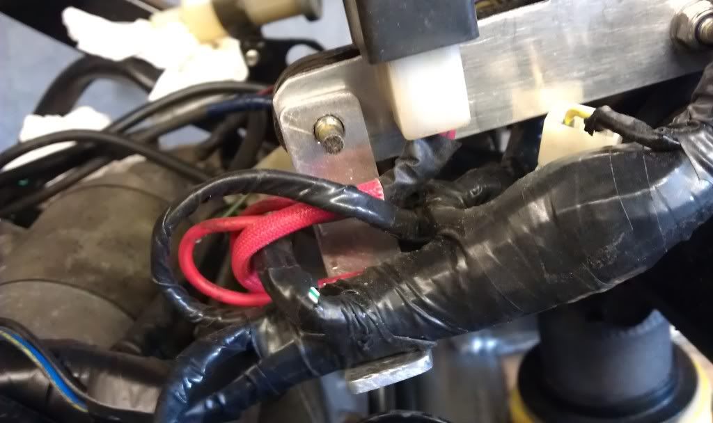
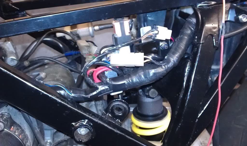
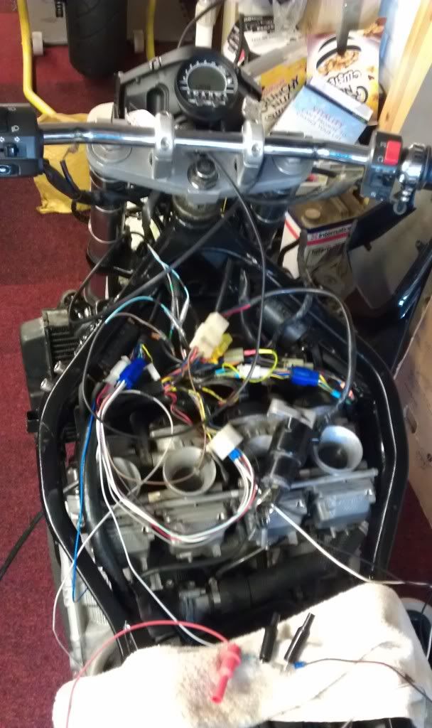
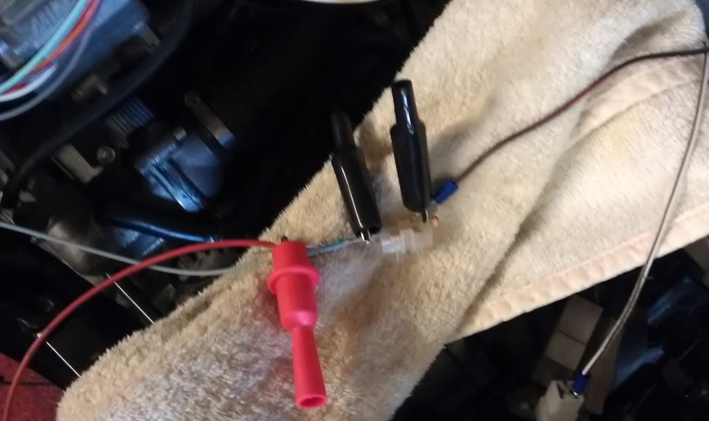
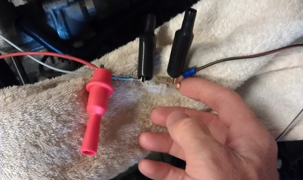
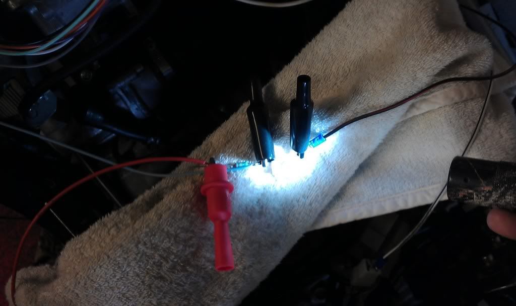
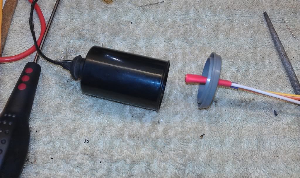
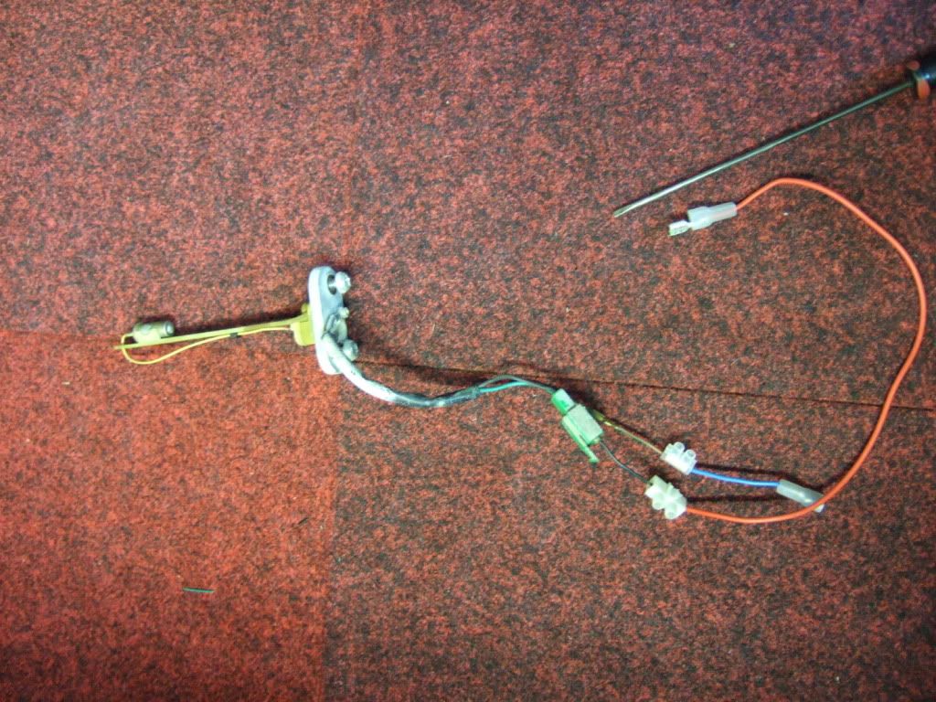
So, i rigged a bulb up across the fuel pump so I could see when it was recieving power

Image

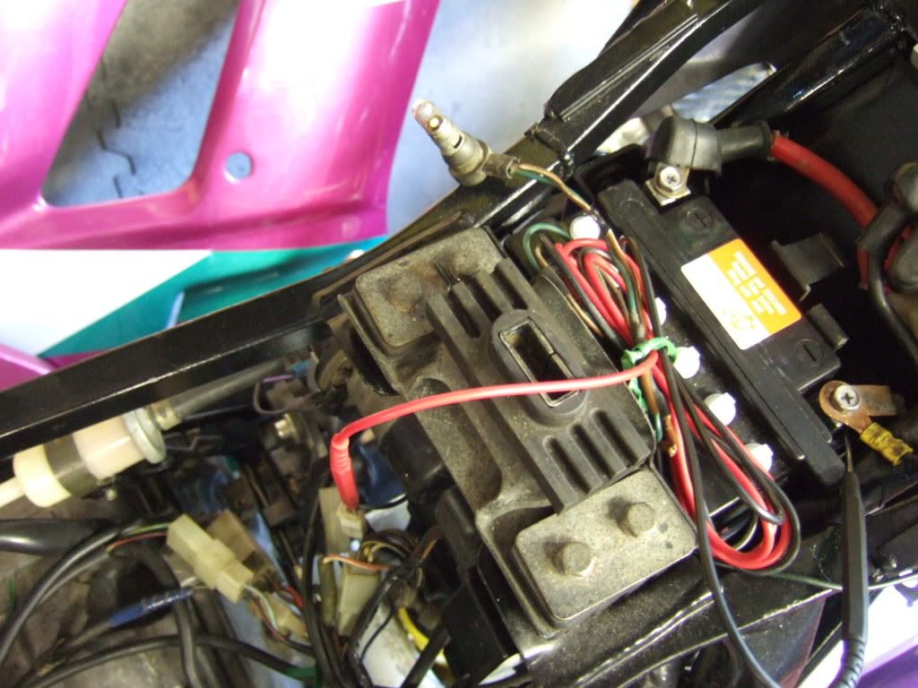
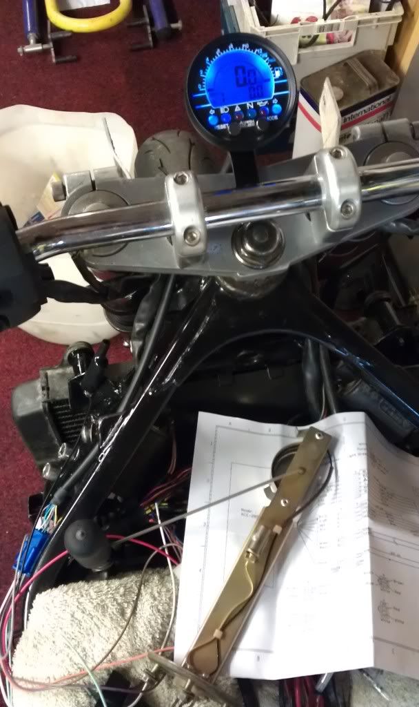
Located the correct wiring for the fuel level light and added a makeshift one.

Image

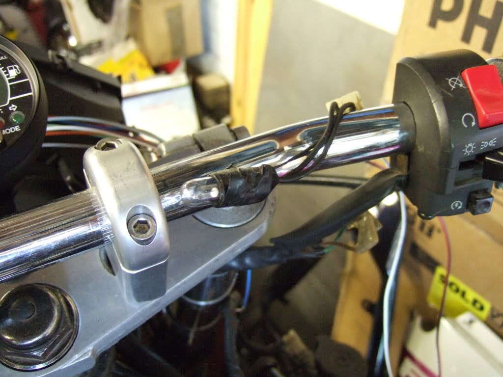
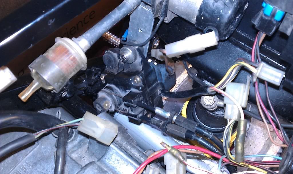
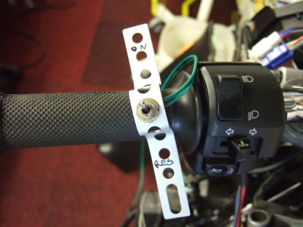
Found the reserve switch wiring and added a switch

Image

Added the sender from the Exup and ran a proof of theory test.

Image

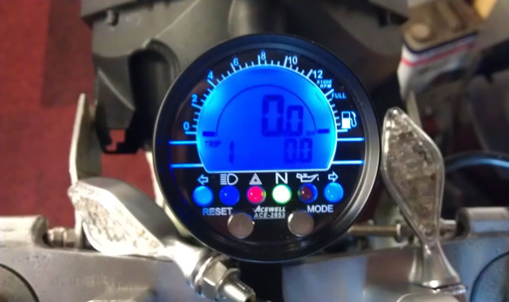
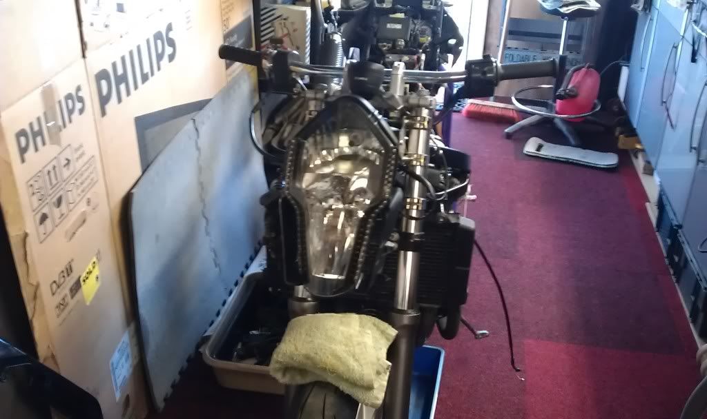
So with the sensor exposed to air, the fuel switch in the on position and the bike running the following should happen.

The bulb across the pump should be on, the fuel light should come on, followed by the pump light turning off, simulating run out of fuel.
Success, the above happened.
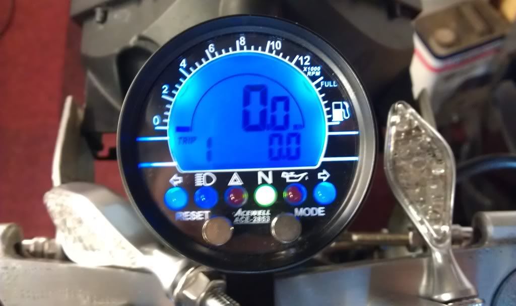
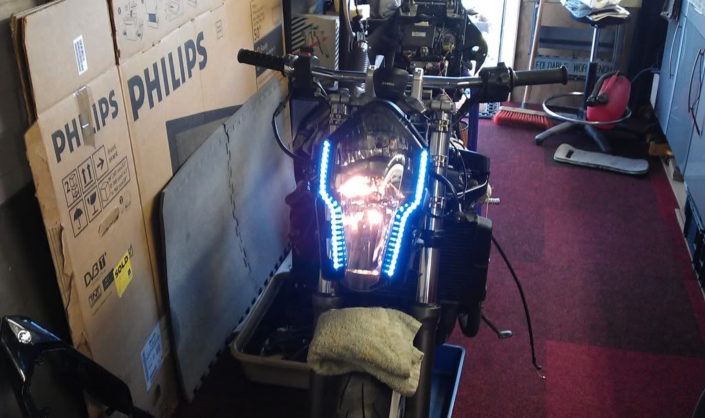
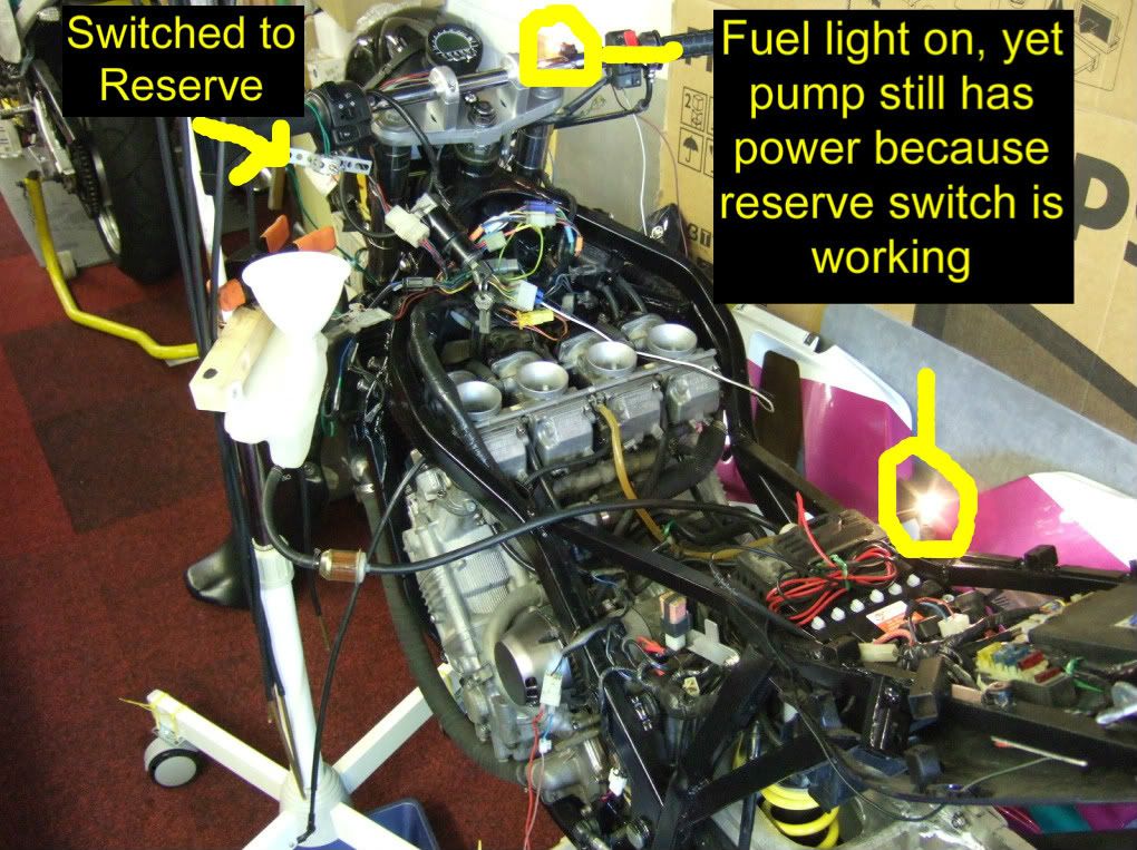
Next theory being that when I flick the switch to reserve power to the pump should return and the pump bulb should illuminate, obviously with the fuel light still lit.
Again success, so we are now effectivley running on reserve.

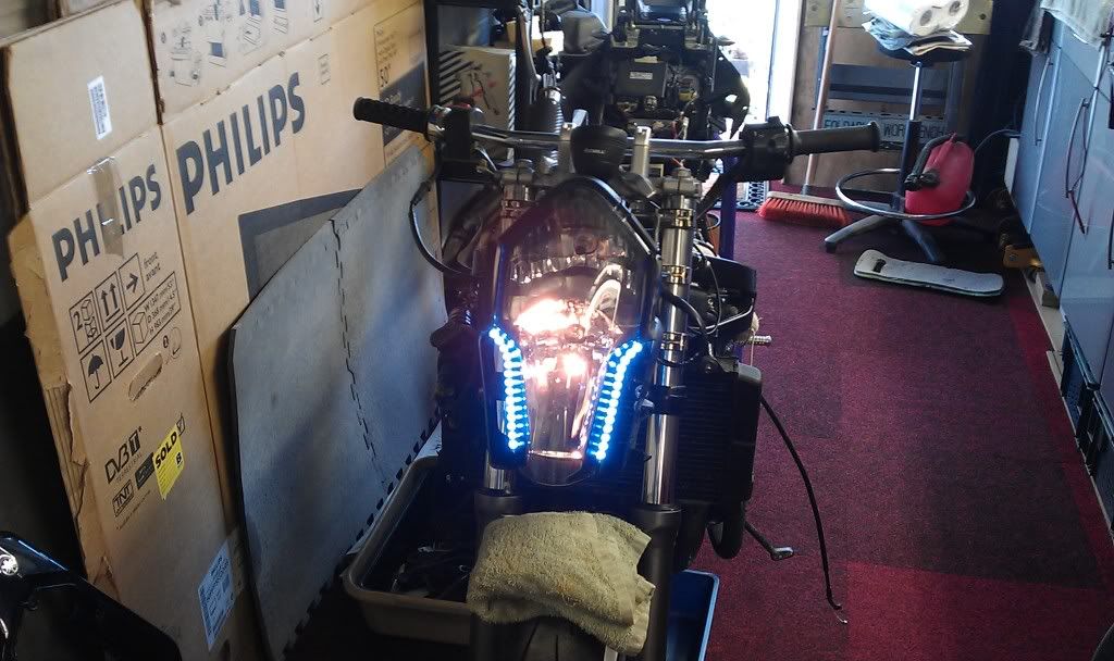
Final test is to immerse the sender in petrol therby simmulating a full tank of fuel which should cause the fuel light to go out yet power remain to the pump.

Again success :D :D :D :D :D :D

Image

So I now have on its way to me a fuel sender from an Exup that I can use to replace the sender in the FZ tank, and have a fully functioning reserve with fuel gauge and fuel level light, bib and braces and all that.

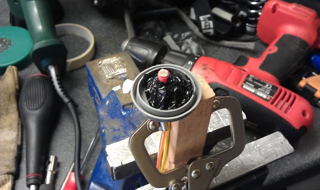
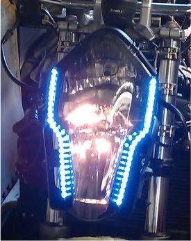
There is one slightly concerning thing I discovered though, its just how "warm" the sensor gets when not cooled by petrol.
This was after a minute's exposure to air, vid below. :eek:

Image

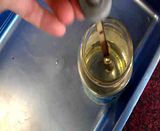
A bit disconcerting but I tested it on the Exup incase it was due to different wiring or voltages, but its the same so try not to think about it next time you fill up after running on reserve for 6 miles or so. :paranoid:

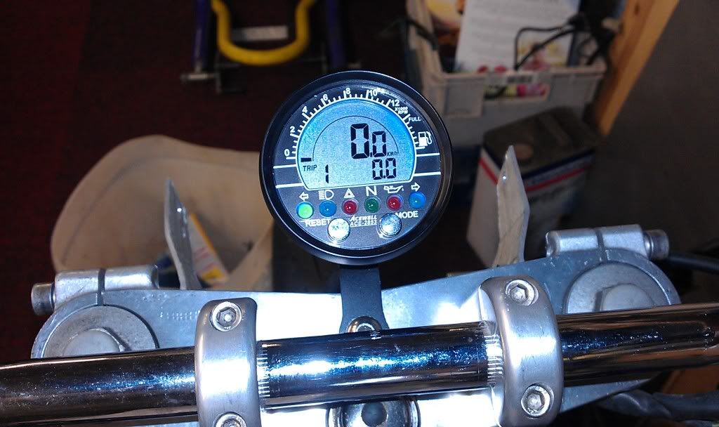
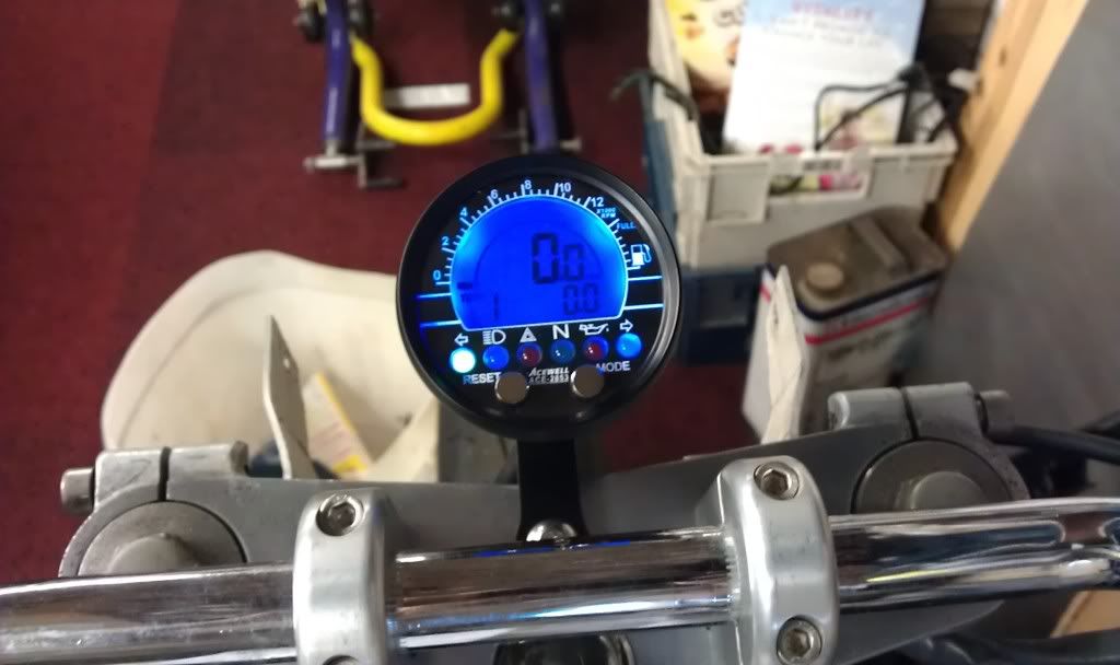
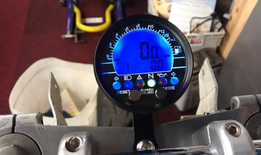
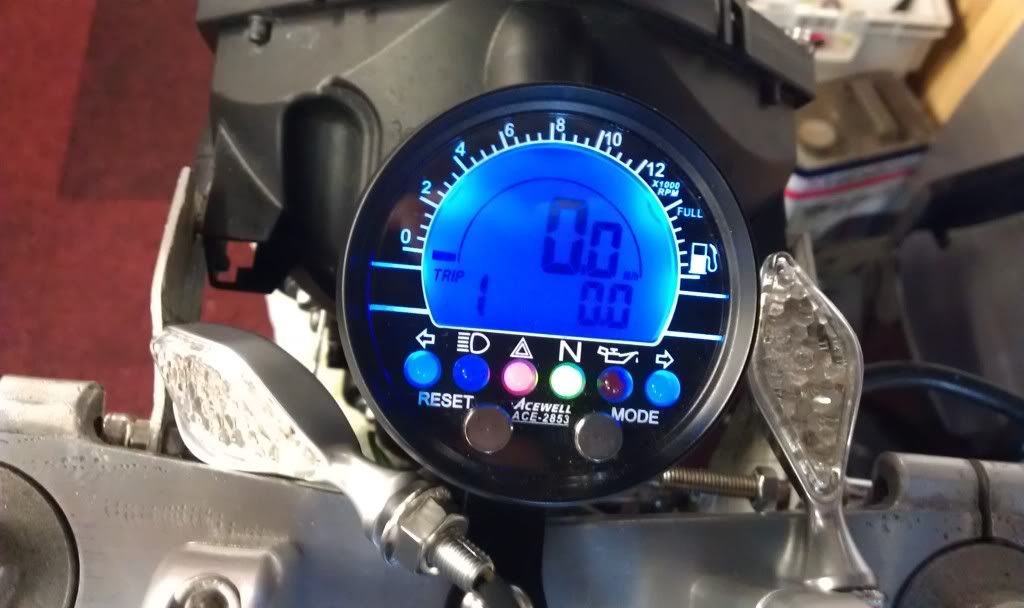
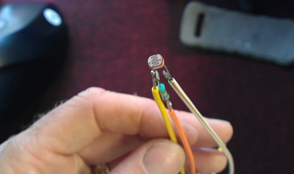
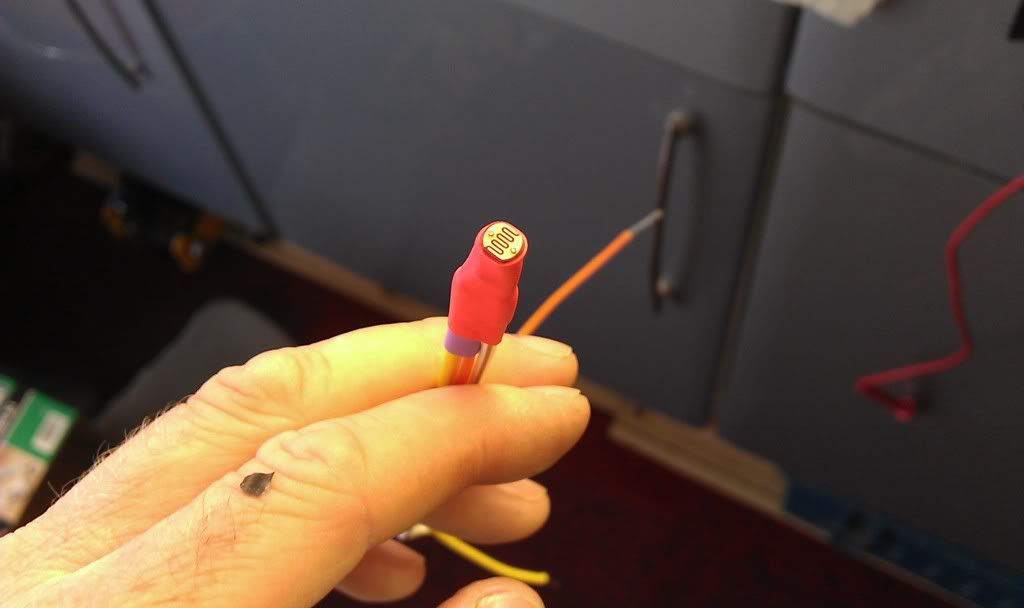
The one final thing I have to do is make a photoresistor relay so I can use the fuel light to turn on the "hazard" LED in the Acewell, but I'm investigating this as I type.
Never Ever Bloody Anything Ever!!!
User avatar
fang
Pit-lane Reporter
Pit-lane Reporter
Posts: 741
Joined: Mon Jun 19, 2006 5:38 pm
Location: Bootiful Norfolk

Post by fang »

Whilst performing the reserve test operation, I kept hearing a tick everyso often, upon investigation it turned out one of the spark caps was duff and the ticking was the spark jumping from the cap to the head.

Image

Vid clip

Image

Took the offending item out to discover a hairline crack in the casting and a completely open circuit when tested with a multimeter.
So a new one has been purchased. :D

Image

Image
Never Ever Bloody Anything Ever!!!
User avatar
fang
Pit-lane Reporter
Pit-lane Reporter
Posts: 741
Joined: Mon Jun 19, 2006 5:38 pm
Location: Bootiful Norfolk

Post by fang »

Right then, petrol sender arrived, but turned out to be DOA so was returned for a refund and another purchased (different supplier) so we'll see how that goes when it turns up.

In the meantime I tried again with the sidelight fixing, this time with some new sealant and insulation tape :D


Image

Image

Image

drilled a couple of small holes in the bottom to run the wiring inside the headlight and connect it to the original side light

Image

Image

Image

24 hours later removed the tape

Bazinga :D

Image

Image

In between doing odds and sods I have also just done the valve clearances on my Exup.

In doing so I realised that it was possible to obtain a false reading due to the fact that a 0.15mm feeler gauge CAN be made to fit in a clearance that is smaller by virtue of the fact that it opens the valve!!

So with this in mind I, reluctantly, revisited the valve clearances on the FZ


Image

worryingly there were 2 inlet clearances that were less than 0.04mm,well below the specified clearance of 0.11-0.20mm, not a problem except one of these had a 1.25 shim fitted meaning it could only be replaced by a 1.20 shim (the thinnest available) bringing the clearance to a max of 0.09mm

Basically the valve seats have receded into the head through wear and all the adjustment has been used so a refurb is called for at some point.

Arse, and she sounds so sweet when running.

Oh well, once the required shims arrive we'll see how she goes. :D
Never Ever Bloody Anything Ever!!!
User avatar
fang
Pit-lane Reporter
Pit-lane Reporter
Posts: 741
Joined: Mon Jun 19, 2006 5:38 pm
Location: Bootiful Norfolk

Post by fang »

Well the shims arrived and I now have the correct clearances.

The down side being that three of the valves have the smallest shims fitted (1.20) so thats the end of adjustment for this head. :crybaby:

Still seeing as I have only done 488 miles in the last 4 years on the Exup I dont think it will be an issue for a little while yet. :lol:

anyhow now that the engine is back together I thought it time to carry on with otherstuff and do a little updating.

Whilst the loom was peeled back from the frame to do the clearances I took the opportunity to add another wire to it for the fuel level sender, which meant unwrapping it and starting again!! :angry:

Made two new brackets, one so the wiring loom doesn't chafe on the side panel mounting lug and one to replace the servo motors temporary mount, and also mounted the LED flasher unit properly.

Image

Loom bracket

Image

Image

Servo bracket

Temporary one

Image

Image

Image

flasher unit installed

Standard unit (right hand side of ally bracket)

Image

Led unit

Image

Next on the list was to remind myself of what connects to what to get the Acewell working, resulting in the following birds nest :lol:

Image

All temp connections before final soldering/tidying.

All worked, plus my solution for using the "hazzard" LED on the acewell as a fuel level light.

The problem being the Acewell needs a 12v supply to the LED to make it light, whereas the fuel light on the YZF750 loom lights because of a voltage drop between two wires ( both of which are at 12v when the "system" is not on reserve) meaning you cant just connect the LED to the Fuel light connection.

So after dismantling a night light to get at the photoresistor I constructed the following, a voltage divider that uses the photoresistor to change the output voltage dependant on light level.

Image

Image

Basically I'll use the standard fuel light to trigger the LED in the Acewell by getting the photoresistor to detect the fuel light coming on. :unibrow:

Photoresistor in ambient light, 5v output to Acewell, LED partially lit.

Image
Image

Photoresistor in darkness, 1v output to Acewell, LED unlit.

Image
Image

Photoresistor in bright light, 11v output to Acewell, LED fully lit.

Image
Image

So now the concept had been proved it was time to sort out a proper solution.

sensor soldered and sealed.

Image
Image

After hunting the house for ages I managed to find a 35mm film casing, remember them? to provide me with a sealable container that I can put the fuel light in one end and the sensor in the other.

Image
Image
Image
Image

Installed for testing,fuel bulb unlit, hazzard LED unlit, fuel bulb lit, hazzard LED lit, result :D

Image

Now all I need is for the replacement fuel sender to arrive and I can sort out connecting everything and that should be the end of the wiring.

One last thing, not sure what looks best for the side lights so opinions please, which looks better?

Image
Image
Image

Let me know what you think. :D
Never Ever Bloody Anything Ever!!!
User avatar
nasty
Pit-lane Reporter
Pit-lane Reporter
Posts: 765
Joined: Mon Feb 12, 2007 8:02 pm
Location: in dark room in the garden

Post by nasty »

both look good to me if thats any help :D
use the best which works the out side and catchs the eye most easy :nod:
nasty`s the name helmet paintins, the game

if not pink don`t lick it!
User avatar
Stig
Site Admin
Site Admin
Posts: 11786
Joined: Wed Sep 28, 2005 7:54 am
Location: Searching for my bike

Post by Stig »

I like the full version

there, I made a decision :nod:
AKA Bald headed b'stard
User avatar
nuggitt
Moderator
Moderator
Posts: 5967
Joined: Fri May 22, 2009 9:45 pm
Location: North Yorkshire

Post by nuggitt »

Think I prefer the full lights too. Looks more eye catching. :nod: :nod:
Bit of advice. Buy a good bed and a good pair of shoes, because if you aren't in one you'll be in the other.
User avatar
mogster
Scooter Boy
Scooter Boy
Posts: 69
Joined: Tue May 13, 2008 10:32 am
Location: Manningtree

Post by mogster »

is it me or does the bottom one look like that painting 'the screem' :nod:
User avatar
fang
Pit-lane Reporter
Pit-lane Reporter
Posts: 741
Joined: Mon Jun 19, 2006 5:38 pm
Location: Bootiful Norfolk

Post by fang »

mogster wrote:is it me or does the bottom one look like that painting 'the screem' :nod:
Dont know what you mean :lol: :lol: :lol:

Image Image

maybe thats what I'll call the bike :unibrow:
Never Ever Bloody Anything Ever!!!
User avatar
Grim Reaper
Commentary Team
Commentary Team
Posts: 842
Joined: Mon Sep 11, 2006 11:00 pm
Location: Scotland

Post by Grim Reaper »

Hats off to you Fang.

I remember reading the start of this thread years ago when you posted the pics showing a slight 'twist' in the front end.

Probably the best thread I've ever followed :)
User avatar
fang
Pit-lane Reporter
Pit-lane Reporter
Posts: 741
Joined: Mon Jun 19, 2006 5:38 pm
Location: Bootiful Norfolk

Post by fang »

Cheers Grim, yep 23rd Feb 2008 is when I picked her up!

Its been a long journey so far, with a few massive pauses.

Solved the frame "twist" issue by getting another one :D

We're getting there now, just got to keep plodding on.

And as for "Probably the best thread I've ever followed" I feel you must have lead a sheltered life :lol: , but thank you :blush:
Never Ever Bloody Anything Ever!!!
Post Reply